1-3
1-4 Structure of the Device and Description of Each Part
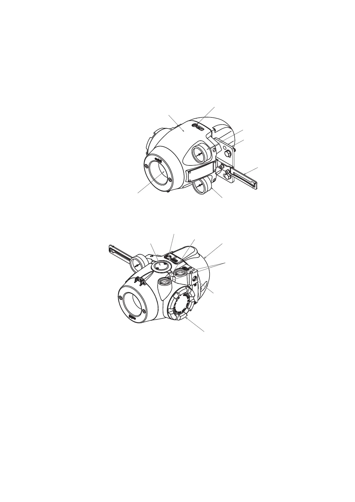
1-4-1 Structure of the Device
1) Major components
The structure of the main unit of the device is shown in the figure below.
Mounting plate (optional)
Feedback lever
Supply air pressure gauge
Main unit
Local user
interface (LUI)
Output air pressure gauge
Output air connection port (OUT1)
Figure1-4 Structure of the Device (Upper)
Electrical conduit connection port
Pilot relay cover
External grounding terminal
Terminal box cover
Exhaust cap
Output air connection port (OUT2)
Supply air connection port (SUP)
Figure1-5 Structure of the Device (Lower)

 Loading...
