1-4
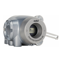
2) Name and description of each part
The table below describes each part.
Table 1-1 Description of Each Part
Name Description
Main unit
- Houses electronic circuits, an electro-pneumatic transducer (EPM), a
position sensor (VTD), and a pressure sensor.
Pilot relay cover
- Cover of the pilot relay that amplifies the air signal from the EPM
(electro-pneumatic transducer) and transduces it into the air signal
sent to the actuator.
- When you must adjust the balance pressure to switch between the
pilot relay for the single-acting actuator and the pilot relay for the
double-acting actuator, remove this cover.
Auto/Manual (A/M) switch
- This switch is used to switch how the output air between the auto
operation status and the manual operation status is controlled.
This switch is built into the pilot relay. This switch can be seen by
removing the pilot relay cover.
Feedback lever
- Extracts and transmits the movement of the control valve lift to the
VTD (position sensor).
Local user interface (LUI)
- The LUI allows you to adjust the zero span, perform auto setup, and
manually operate the device with the LCD (liquid crystal display) and
operation buttons without using the communicator.
Supply air pressure gauge - Indicates the pressure of supply air.
Output air pressure gauge - Indicates the pressure of output air.
Supply air connection port (SUP)
- Supply air is input to this port.
- “SUP” is displayed at this port.
Output air connection port (OUT1)
- Output air is sent out of this port to the actuator.
- “OUT1” is displayed at this port.
Output air connection port (OUT2)
- Output air is sent out of this port to the actuator.
- This port is blocked with a blind plug in the single-acting actuator.
- OUT2 is displayed at the output port for the double-acting actuator.
Mounting plate (optional)
- The mounting plate is used to mount the device onto the actuator.
- The shape of the mounting plate differs depending on the
specifications (actuator model).

 Loading...