1-6
2) Name and description of each part
The table below describes each part of the terminal box.
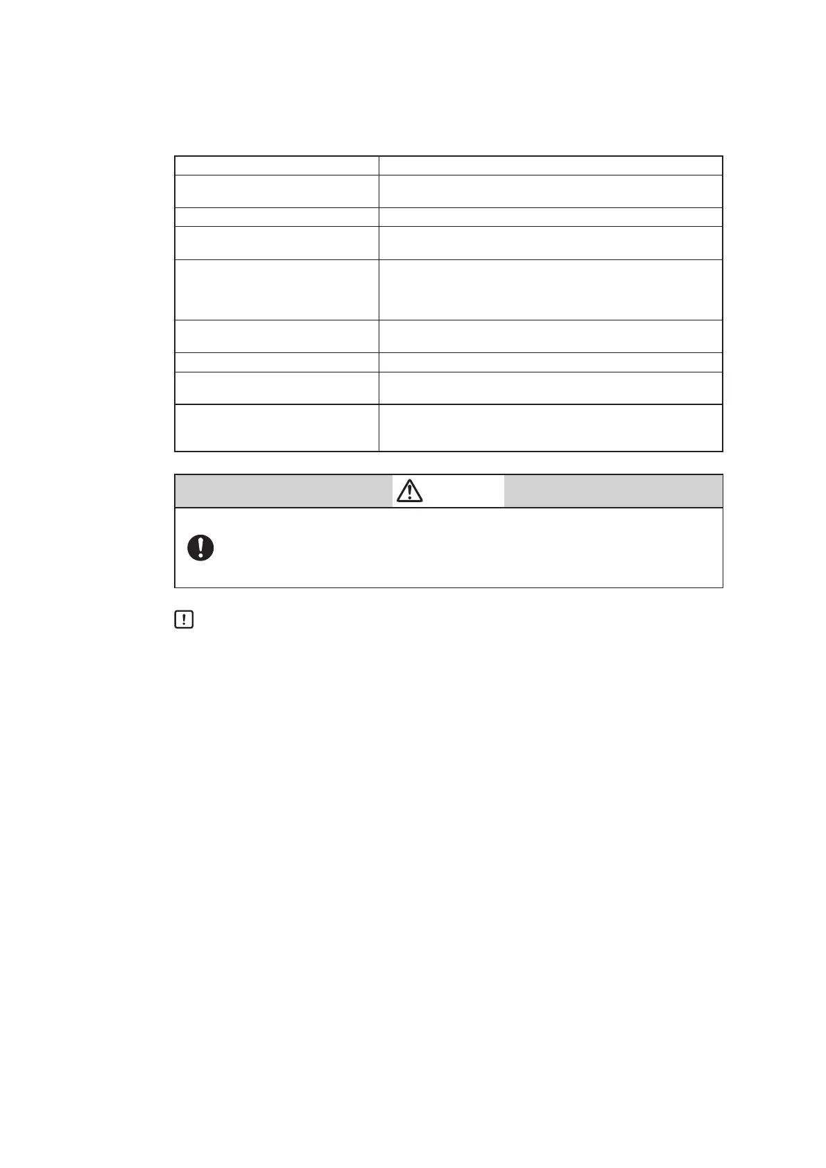
Table 1-2 Description of Each Part
Name Description
Terminal box cover
- Lid of terminal box.
- This cover has a pressure-resistant explosion-proof structure.
Lock screw - Used to secure the terminal box cover.
Terminal for input signals
- Shown as IN.
- Connects the signal cable from the host controller.
Terminal for output signalsl
- Shown as OUT.
- Connects the signal cable for motion transmission.
- The AVP702 model (without motion transmission) does not have
the terminal screws.
Internal grounding terminal
- Internal terminal for grounding. The cable for grounding is
connected to this terminal.
Conduit connection port (1) - Service entrance for a cable.
Conduit connection port (2)
- Service entrance for a cable.
- This entrance is normally blocked with a blind plug.
Check pin for HART communication
- By connecting the connection hook for the setting device
communication cable to this pin, it is possible to communicate
with this device.
Warning
When using a pressure-resistant explosion-proof model in a dangerous place,
be sure to use the specified cable adapter for pressure-resistant packing for
the conduit connection port. Securely close the terminal box cover all the way.
Then, rotate the lock screw counterclockwise to secure the terminal box cover.
Handling Precautions:
Ground either the external or internal grounding terminal according to the
specifications. Be careful not to ground the device at two points.

 Loading...
