2-6
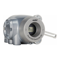
1) Mounting the feedback lever
Assemble the feedback lever from the front of the main unit of the device using the two
included hexagon socket bolts.
Figure 2-1 Mounting Procedure for Feedback Lever
Assemble the extension lever as shown in the figure below if necessary.
Figure 2-2 Mounting Procedure for Extension Lever
2) Mounting example
A typical mounting method is shown in the figure below. If your actuator is not shown in
the figure below, refer to the assembly diagram included with the device.
[Direct-Acting Actuator HA2 to 4, PSA1 to 4, 6, VA1 to 6 from Azbil Corporation]
Plain washer
Hexagon socket flange bolts (x 2)
Connector pin assembly
Feedback lever
Feedback pin
Spring washer
Figure 2-3 Mounting Procedure for Direct-Acting Actuator HA2 to 4, PSA1 to 4, 6, VA1
to 6 from Azbil Corporation
[RSA1, 2, VR3 actuator from Azbil Corporation]

 Loading...