6-3
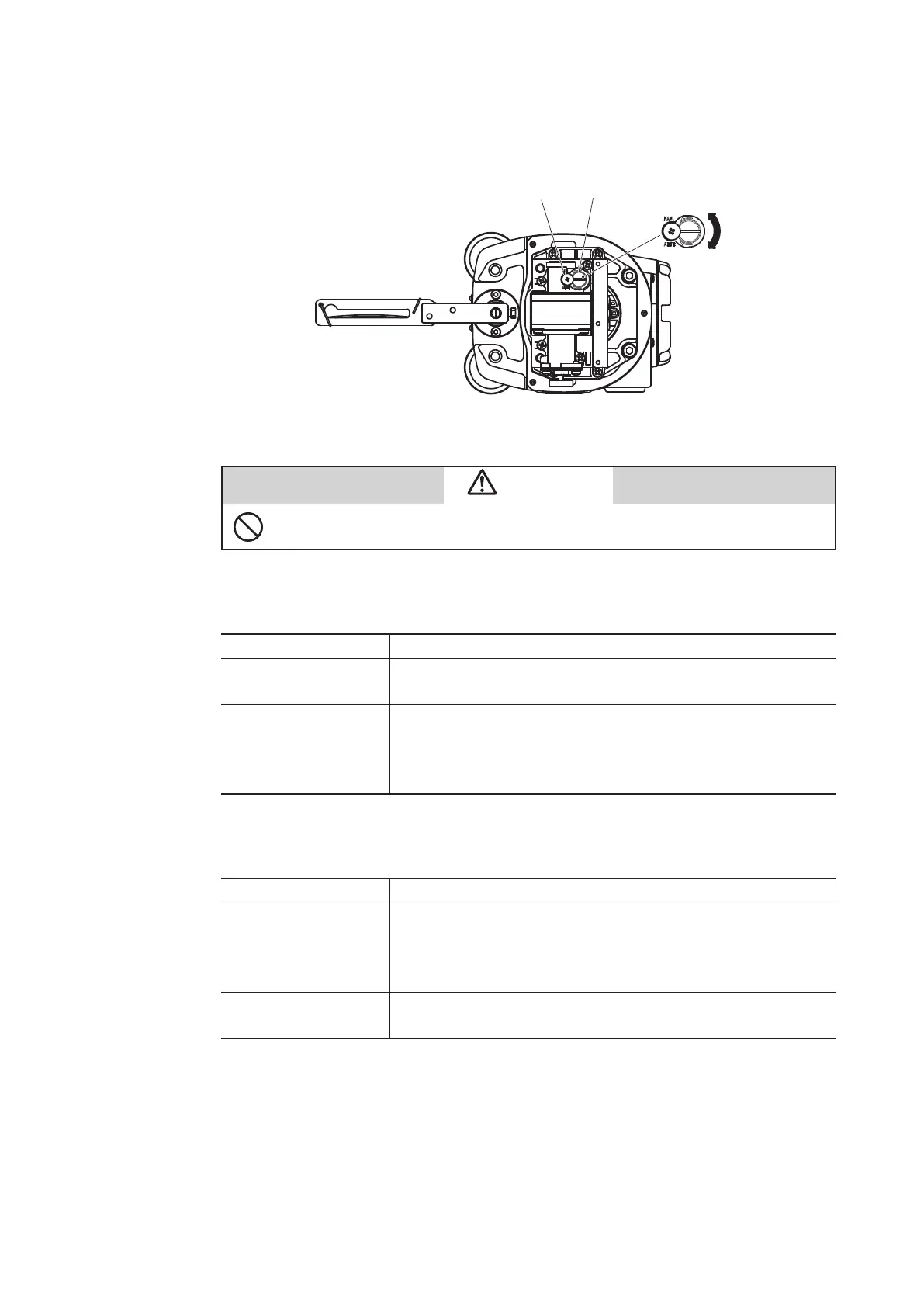
3) Structure of A/M switch
The structure of the A/M switch is shown in the figure below.
Remove the pilot relay cover.
AUTO
Figure 6-1 Structure of A/M Switch
Cautions
Do not loosen the setscrew. If the setscrew is loosened, the A/M switch will pop
out due to the air pressure, potentially causing an injury.
4) Procedure for switching from auto operation to manual operation
The procedure for switching from auto operation to manual operation is shown below.
Step Work
1
Loosen the three screws to remove the pilot relay cover in
order to operate the A/M switch.
2
Rotate the A/M switch counterclockwise (in the MAN direction)
by one revolution using a flat-head screwdriver. (Confirm
that operation has switched by using the output air pressure
gauge.)
5) Procedure for switching from manual operation to auto operation
The procedure for switching from auto operation to manual operation is shown below.
Step Work
1
Securely rotate the A/M switch clockwise (in the AUTO
direction) using a flat-head screwdriver until it stops. (Confirm
that operation has switched by using the output air pressure
gauge.)
2
Attach the pilot relay cover onto the main unit with the three
screws.

 Loading...
