3-11
Chapter 3. MOUNTING AND WIRING
z
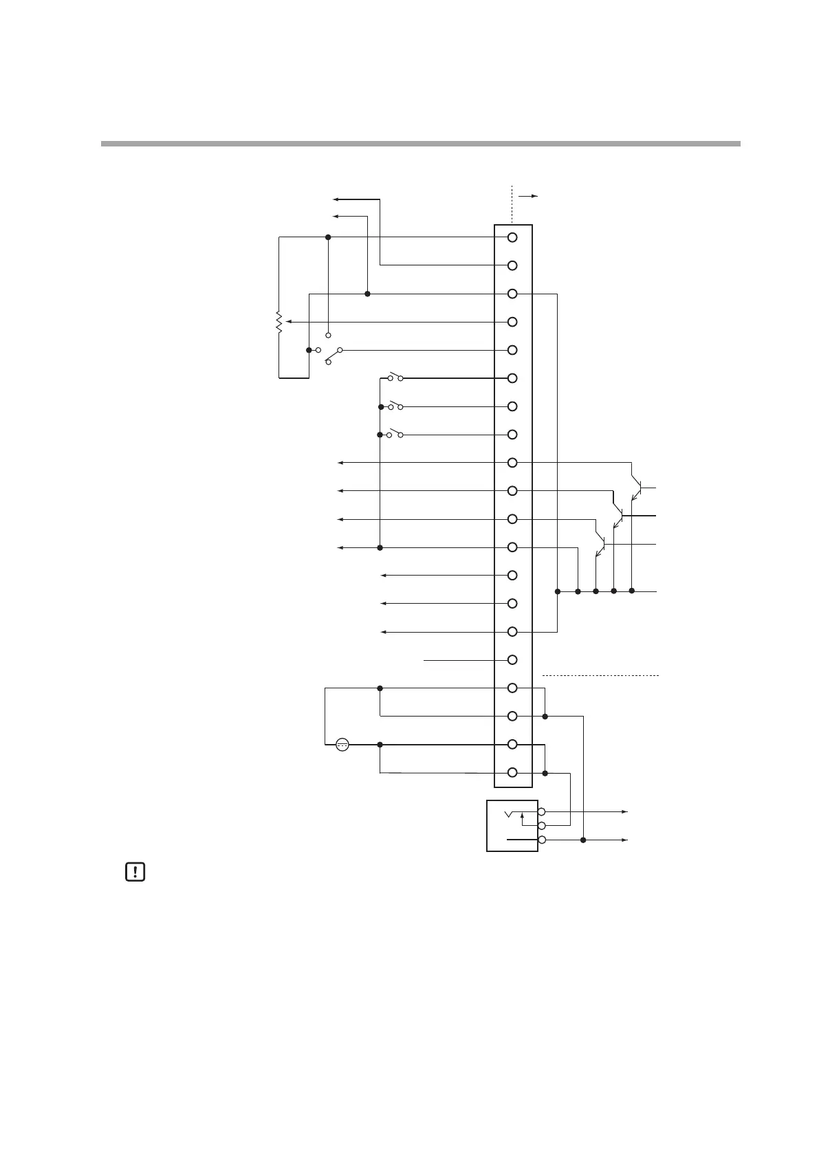
Example of wiring
20
19
18
17
16
15
14
13
12
11
10
9
8
7
6
5
4
3
2
1
+5 V (5 mA max.)
FLOW OUT
A.GND
FLOW SP INPUT
MODE INPUT
DI3
DI2
DI1
EV2 OUT
EV1
OUT
ALM OUT
D.GND
DB
DA
D. GND
TEST
POWER GND
POWER GND
POWER (24 V)
POWER (24 V)
Internal circuit
Power circuit
AC adapter input
Power supply
(24 V DC)
Event output 2
Event output 1
Alarm output
(Output common)
Instantaneous owrate output
+
-
+5 V
0 V
OPEN
+
-
+
-
DB
DA
SG
Potentiometer
(5 kΩ)
Handling Precautions
•
Do not input any signal to pin No. 5.
•
The power circuit is isolated from the input/output circuit inside this device.
•
Even though the analog GND and digital GND are connected internally, always
carry out the grounding wiring individually.
•
When the AC adapter plug is inserted into the AC adapter power supply
terminal, the power supply changes from the DC power supply to the AC
adapter.
•
The former AC adapter 81446682-001 (15 V DC, 350 mA) cannot be used with
this device.