1-1
Chapter 1.
PRELIMINARIES
Names and function of parts
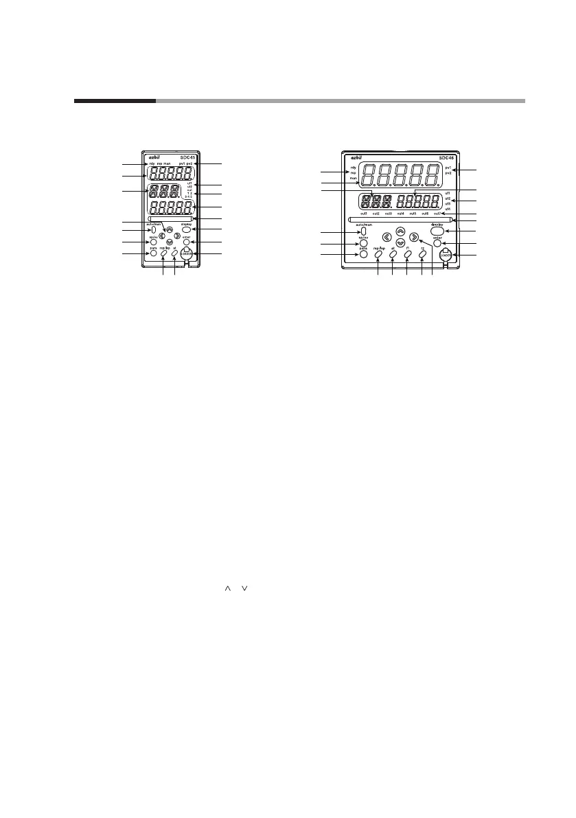
Front panel of SDC45 Front panel of SDC46
(15)(16)
(3)
(1)
(5)
(5)
(3)
(1)
(9)
(8)
(9)
(10)
(12)
(10)
(12)
(15)(16)
(14) (14)
(8)
(13)
(11)
(17)
(13)
(11)
(17)
(2)
(4)
(7)
(5)
(6)
(4)
(5)
(6)
(7)
(2)
Description
(1) Upper display: Displays PV (present temperature etc.) or setup
items.
(2) Lower display: Displays SP (set temperature, etc.) and other
parameters.
(3) Auxiliary display: Displays user-defined operation display No. and
group No., loop No., and channel No. of items
available for setup.
*: The series of connections from PV input to PID operation
through to control output is generically called a loop.
(4) Multi-status indicator:
Indicates MV or DI/DO status.
(5) Mode indicators:
rdy: Lights up in READY mode.
rsp: Lights up in RSP (remote setting input) mode.
man: Lights up in MANUAL mode.
out1-7: Light up when the output is ON (SDC45: out1-5).
Always lit when the output is current or continu-
ous voltage.
(6) User function indicators:
uf1-4: Light under user-assigned conditions (SDC45: uf1,
uf2).
(7) Loop number indicators:
pv1, pv2: Light up to indicate which loop has the displayed
PV value.
(8) [
], [ ],[<], [>] keys:
Used to increment/decrement numeric values and
shift between digits or settable items.
(9) [auto/man] key: Used to change AUTO/MANUAL mode.
(10) [sp/ev] key: Used to set the SP/EV bank.
(11) [display] key: Used to change the display contents in the opera-
tion display mode.
(12) [para] key: Used to set the PARA bank.
(13) [enter] key: Used in initiating setup and to confirm changed
values.
(14) [f1], [f2] key: Used for user-assigned functions. (SDC46 only).
(15) [at] key: Used to execute/cancel auto-tuning, or for user-
assigned functions.
(16) [rsp/lsp] key: Used to change between remote and local set
point, or for user-assigned functions.
(17) Loader jack: Jack for connection of PC loader cable (with cap).