2-13
Chapter 2. PARA BANK SETTINGS
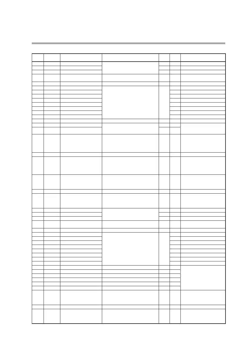
MV bank (Mv)
Display
Loop number
(auxiliary display)
Item Settings and descriptions Initial
value
User
setting
Remarks
Mv-0 1 L. 1.
Output at READY -10.0 to +110.0 % 0.0
Mv-02 L. 1.
Output at READY (heat) 0.0
Mv-03 L. 1.
Output at READY (cool) 0.0
Mv-04 L. 1.
Output operation at PV alarm 0: Control calculations continue
1: MV is output if PV is abnormal
0
Mv-05 L. 1.
Output at PV alarm -10.0 to +110.0 % 0.0
Mv-06 L. 1.
Fixed value output 1 -10.0 to +110.0 % 0.0
Mv-07 L. 1.
Fixed value output 2
Mv-08 L. 1.
Fixed value output 3
Mv-09 L. 1.
Fixed value output 4
Mv- 10 L. 1.
Fixed value output 5
Mv- 1 1 L. 1.
Fixed value output 6
Mv- 12 L. 1.
Fixed value output 7
Mv- 13 L. 1.
Fixed value output 8
CaS.0 1 L. 1.
Scaling system 0: Fixed 1: SP reference 2: PV reference 0
CaS.02 L. 1.
Scaling low limit -19999 to +32000 U 0.0 The decimal point position is
determined by the decimal point
positions for the loop PV/SP.
CaS.03 L. 1.
Scaling high limit 1000.0
CaS.04 L. 1.
Tracking mode 1024: OFF 1025: ON 152: DI-C1
1153: DI-C2 1154: DI-C3 1155: DI-C4
1156: DI-C5 1157: DI-C6 1158: DI-C7
1159: DI-C8 1176: DI-F1 1177: DI-F2
Others
1024 Setting range is 1024 to 2047
For details, refer to:
Standard bit codes (P.4-1).
CaS.05 L. 1.
SP output filter 0.00: No filter 0.01 to 120.00 s 0.00
CaS.06 L. 1.
SP tracking signal 2048 to 3071 2048 Cannot be on the SDC45A/46A/
45R/46R.
For the SDC45V/46V, see the
Standard numerical codes
(P.4-3).
TR-0 1 L. 1.
MV tracking selection 0: OFF
1: Output of input computation F7
2: Output of output computation F7
Others
0 Setting range is 0 to 2047.
For more details on the 1024 to
2047 range, see the: Standard bit
codes (P.4-1).
TR-02 L. 1.
Reverse MV tracking signal 0: Direct 1: Reverse 0
TR-03 L. 1.
MV tracking signal 0: 0% fixed
1: Output of input computation F7
2: Output of output computation F7
Others
0 Setting range is 0 to 3071.
For more details on the 2048 to
3071 range, see the: Standard
numerical codes (P.4-3).
Mv-0 1 L.2.
Output at READY -10.0 to +110.0 % 0.0
Mv-02 L.2.
Output at READY (heat) 0.0
Mv-03 L.2.
Output at READY (cool) 0.0
Mv-04 L.2.
Output operation at PV alarm 0: Control calculations continue
1: MV is output if PV is abnormal
0
Mv-05 L.2.
Output at PV alarm -10.0 to +110.0 % 0.0
Mv-06 L.2.
Fixed value output 1 -10.0 to +110.0 % 0.0
Mv-07 L.2.
Fixed value output 2
Mv-08 L.2.
Fixed value output 3
Mv-09 L.2.
Fixed value output 4
Mv- 10 L.2.
Fixed value output 5
Mv- 1 1 L.2.
Fixed value output 6
Mv- 12 L.2.
Fixed value output 7
Mv- 13 L.2.
Fixed value output 8
CaS.0 1 L.2.
Scaling system - Cannot be set.
CaS.02 L.2.
Scaling low limit -
CaS.03 L.2.
Scaling high limit -
CaS.04 L.2.
Tracking mode -
CaS.05 L.2.
SP output filter -
CaS.06 L.2.
SP tracking signal -
TR-0 1 L.2.
MV tracking selection 0: OFF
1: Output of input computation F7
2: Output of output computation F7
Others
0 Setting range is 0 to 2047.
For more details on the 1024 to
2047 range, see the: Standard bit
codes (P.4-1).
TR-02 L.2.
Reverse MV tracking signal 0: Direct 1: Reverse 0
TR-03 L.2.
MV tracking signal 0: 0% fixed
1: Output of input computation F7
2: Output of output computation F7
Others
0 Setting range is 0 to 3071.
For more details on the 2048 to
3071 range, see the: Standard
numerical codes (P.4-3).