2-16
Chapter 2. PARA BANK SETTINGS
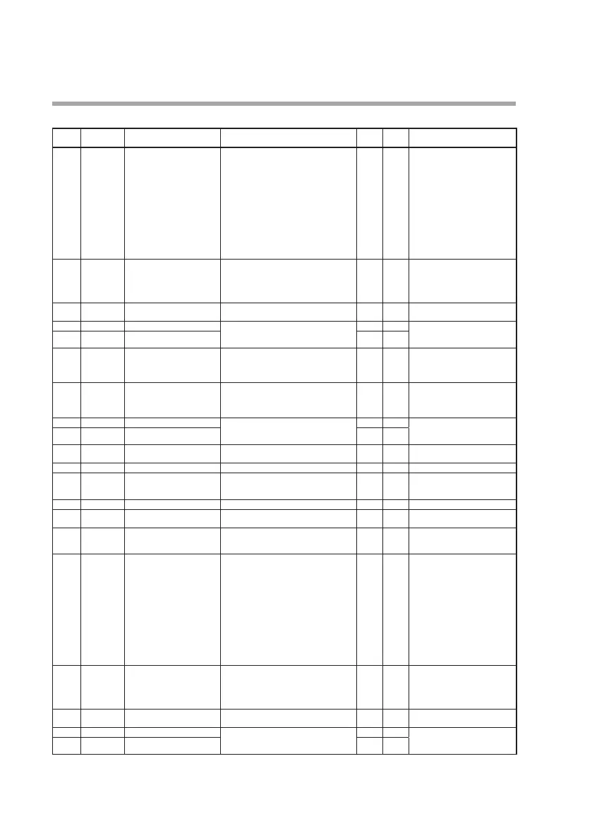
PV bank (pv)
Display
PV input number
(auxiliary display)
Item Settings and descriptions Initial
value
User
setting
Remarks
Pv-0 1 1.
Range type 0: Not used 1: K 2: E 3: J 4: T 5: B
6: R 7: S 8: WRe5-26 9: PR40-20
10: Ni-NiMo 11: N 12:PLII 13: DIN U
14: DIN L 15: Au-Fe
21: Pt100 -200 to +850 °C
22: Pt100 -200 to +300 °C
31: JPt100 -200 to +640 °C
32: JPt100 -200 to +300 °C
41: 4 to 20 mA 42: 0 to 20 mA
43: 0 to 10 mV 44: -10 to +10 mV
45: 0 to 100 mV 46: -100 to +100 mV
47: 0 to 1 V 48: -1 to +1 V 49: 1 to 5 V
50: 0 to 5 V 51: 0 to 10 V
51 For details, refer to the PV input
range table in the SDC45/46
Installation Instructions (No.
CP-UM-5445E). Be sure not to set
a range type number that is not
supported.
Pv-02 1.
Decimal point position 0: No decimal point
1: 1 digit after decimal point
2: 2 digits after decimal point
3: 3 digits after decimal point
4: 4 digits after decimal point
1
Pv-03 1.
Temperature unit 0: Celsius (°C) 1: Fahrenheit (°F)
2: Kelvin (K)
0
Pv-04 1.
Range low limit -19999 to +32000 U
-1999.9
The decimal point position is
determined by the decimal point
position for the PV.
Pv-05 1.
Range high limit 3200.0
Pv-06 1.
Cold junction compensation 0: Performed (internal)
1: Not performed (external)
2: Terminal temperature compensation is
done by a sensor on another channel.
0
Pv-07 1.
Zener barrier adjustment -20.00 to +20.00 Ω 0.00 Set by means of the adjustment
procedure.
Cannot be set by direct input of
a numerical value using the keys.
Pv-09 1.
Linear scaling low limit -19999 to +32000 U 0.0 The decimal point position is
determined by the decimal point
position for the PV.
Pv- 10 1.
Linear scaling high limit 1000.0
Pv- 1 1 1.
Square root extraction
dropout
0.0: Square root extraction is not per-
formed 0.1 to 10.0 %
0.0
Pv- 12 1.
Filter 0.00: No filter 0.01 to 120.00 s 0.00
Pv- 13 1.
Bias -19999 to +32000 U 0.0 The decimal point position is
determined by the decimal point
position for the PV.
Pv- 14 1.
Ratio 0.001 to 32.000 1.000
Pv- 16 1.
Thermocouple mV input
burnout
0: Upscale at burnout
1: No burnout detection
0
Pv-20 1.
Linearization table group
definition
0: Disabled 1: Group 1 2: Group 2
3: Group 3 4: Group 4 5: Group 5
6: Group 6 7: Group 7 8: Group 8
0
Pv-0 1 2.
Range type 0: Not used 1: K 2: E 3: J 4: T 5: B
6: R 7: S 8: WRe5-26 9: PR40-20
10: Ni-NiMo 11: N 12: PLII
13: DIN U 14: DIN L 15: Au-Fe
21: P t100 -200 to +850 °C
22: Pt100 -200 to +300 °C
31: JPt100 -200 to +640 °C
32: JPt100 -200 to +300 °C
41: 4 to 20 mA 42: 0 to 20 mA
43: 0 to 10 mV 44: -10 to +10 mV
45: 0 to 100 mV 46: -100 to +100 mV
47: 0 to 1 V 48: -1 to +1 V
49: 1 to 5 V 50: 0 to 5 V 51:0 to 10 V
51 For details, refer to the PV input
range table in the SDC45/46
Installation Instructions (No. CP-
5445E). Be sure not to set a
range type number that is not
supported.
Pv-02 2.
Decimal point position 0: No decimal point
1: 1 digit after decimal point
2: 2 digits after decimal point
3: 3 digits after decimal point
4: 4 digits after decimal point
1
Pv-03 2.
Temperature unit 0: Celsius (°C) 1: Fahrenheit (°F)
2: Kelvin (K)
0
Pv-04 2.
Range low limit -19999 to +32000 U
-1999.9
The decimal point position is
determined by the decimal point
position for the PV.
Pv-05 2.
Range high limit 3200.0