2-32
Chapter 2. PARA BANK SETTINGS
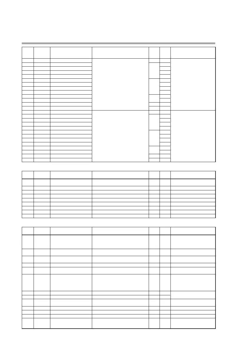
Display
Logical opera-
tion number
(auxiliary display)
Item Settings and descriptions Initial
value
User
setting
Remarks
bF-0
1
15.
Operation type Same as logical operation 1
1
Same as logical operation 1
bF-02
15.
Input assignment A 1024
bF-03
15.
Input assignment B
bF-04
15.
Input assignment C
bF-05
15.
Input assignment D
bF-06
15.
Input bit polarity A 0
bF-07
15.
Input bit polarity B
bF-08
15.
Input bit polarity C
bF-09
15.
Input bit polarity D
bF-
10
15.
ON delay time 0.0
bF-
1
1
15.
OFF delay time
bF-
12
15.
Polarity 0
bF-
13
15.
Latch 0
bF-0
1
16.
Operation type Same as logical operation 1
1
Same as logical operation 1
bF-02
16.
Input assignment A 1024
bF-03
16.
Input assignment B
bF-04
16.
Input assignment C
bF-05
16.
Input assignment D
bF-06
16.
Input bit polarity A 0
bF-07
16.
Input bit polarity B
bF-08
16.
Input bit polarity C
bF-09
16.
Input bit polarity D
bF-
10
16.
ON delay time 0.0
bF-
1
1
16.
OFF delay time
bF-
12
16.
Polarity 0
bF-
13
16.
Latch 0
User-defined bank (udb)
Display Auxiliary
display
Item Settings and descriptions Initial
value
User
setting
Remarks
UDB.AL
-
User-defined bits 1 to 8 00000 to 000FF (hexadecimal value) 00000 User-defined bits 1 to 8 are set
at one time.
UDB.0
1
-
User-defined bit 1
On: ON Off: OFF
OFF
UDB.02
-
User-defined bit 2
On: ON Off: OFF
OFF
UDB.03
-
User-defined bit 3
On: ON Off: OFF
OFF
UDB.04
-
User-defined bit 4
On: ON Off: OFF
OFF
UDB.05
-
User-defined bit 5
On: ON Off: OFF
OFF
UDB.06
-
User-defined bit 6
On: ON Off: OFF
OFF
UDB.07
-
User-defined bit 7
On: ON Off: OFF
OFF
UDB.08
-
User-defined bit 8
On: ON Off: OFF
OFF
Temperature and pressure compensation bank (PV.CMP)
Display Auxiliary
display
Item Settings and descriptions Initial
value
User
setting
Remarks
PV.C.0
1
Compensation method 0: No compensation
1: Temperature compensation
2: Pressure compensation
3:
Temperature and pressure compensation
0
PV.C.02
Unit for temperature
correction
0: Celsius (°C) 1: Fahrenheit (°F)
2: Kelvin (K)
0 Setting cannot be changed if PV
1 is a thermocouple or RTD.
PV.C.03
Design temperature for tem-
perature correction
-1999.9 to +3200.0 0.0
PV.C.04
Unit for pressure correction 0: MPa 1: kPa 2: Pa 3: kg/cm
2
4: mmH
2
0 0
PV.C.05
Design pressure for pressure
correction
-1999.9 to +3200.0 0.0
PV.C.06
Decimal point position
(for flow rate setting)
0: No decimal point
1: 1 digit after decimal point
2: 2 digits after decimal point
3: 3 digits after decimal point
4: 4 digits after decimal point
1
PV.C.07
Flow rate scaling low limit -19999 to +32000 0.0 The decimal point position is
determined by the decimal.
PV.C.08
Flow rate scaling high limit 100.0
PV.C.09
Square root extraction
dropout
0.0: Square root extraction is not per-
formed 0.1 to 10.0 %
0.0
PV.C.
10
Filter 0.00: No filter 0.01 to 120.00 s 0.0
PV.C.
1
1
Bias -19999 to +32000 0.0
PV.C.
12
Ratio 0.001 to 32.000 1.000
PV.C.
13
Linearization table group
definition
0: Disabled 1: Group 1 2: Group 2
3: Group 3 4: Group 4 5: Group 5
6: Group 6 7: Group 7 8: Group 8
0