2-33
Chapter 2. PARA BANK SETTINGS
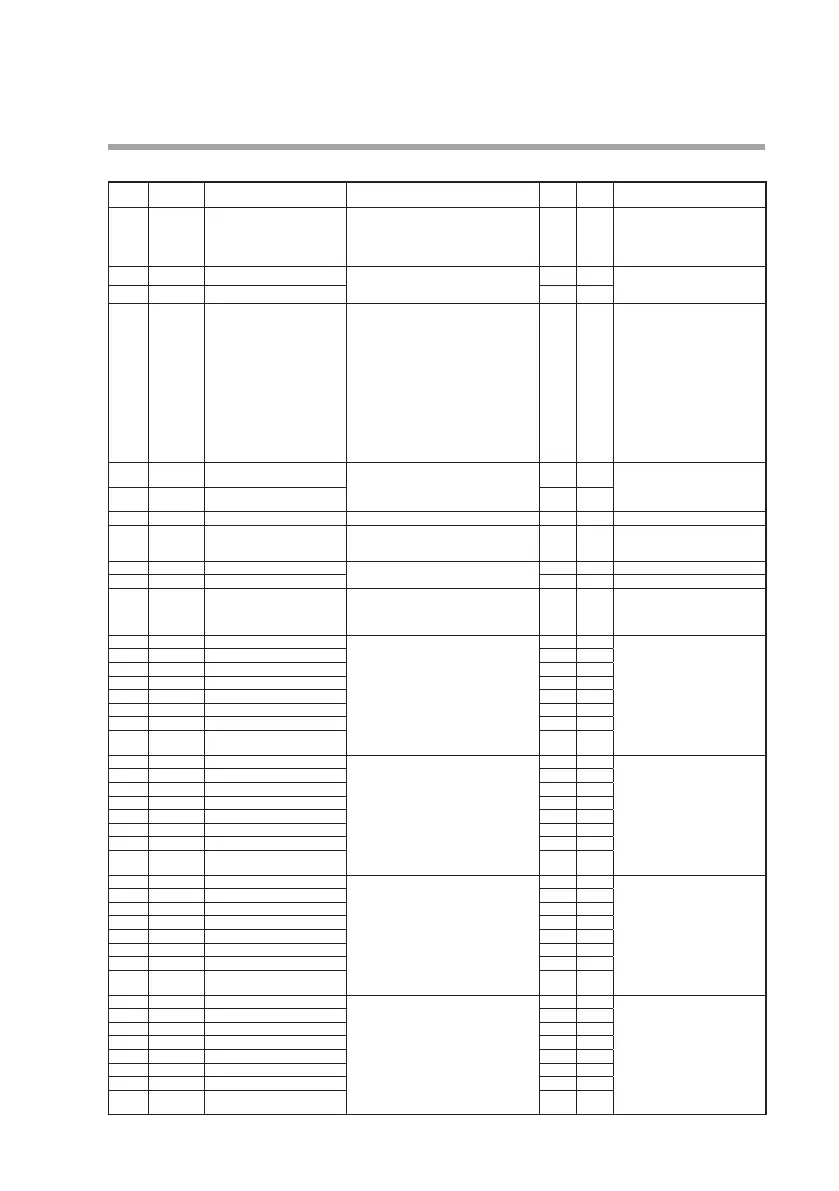
Input computation bank (I N.FNC)
Display Auxiliary
display
Item Settings and descriptions Initial
value
User
setting
Remarks
DP F0 1.
Decimal point position 0: No decimal point
1: 1 digit after decimal point
2: 2 digits after decimal point
3: 3 digits after decimal point
4: 4 digits after decimal point
1
I N.0 1 F0 1.
Input 1 2048 to 3071 2048 For more details on the 2048 to
3071 range, see the Standard
numerical codes (P.4-3).
I N.02 F0 1.
Input 2 2048
TYPE F0 1.
Mathematical/logical
operations
0: NOP No operation
1: FLT First-order lag filter
2: R/B Ratio/bias
3: HLL High/low limiter
4: DRL Change rate limiter
5: LED Differentiation
6: L/L Advance/delay
7: ABS Absolute value
8: TBL Linearization table
9: MAX Maximum value hold
10: MIN Minimum value hold
11: HLD Hold
12: PRS Preset value
13: SPR Soft preset value
0
PA-0 1 F0 1.
Setting 1 -19999 to +32000 U 0.0 The decimal point position is
determined by the setting for
the decimal point position in
the input computation bank.
PA-02 F0 1.
Setting 2 0.0
PA-03 F0 1.
Setting 3 0 to 255 0
DI .SEL F0 1.
Contact input 1024 to 2047 1024 For more details on the 1024 to
2047 range, see the Standard
bit codes (P.4-1).
DI F0 1.
Contact input monitor 0: OFF 1: ON -
DO F0 1.
Contact output monitor -
OUT F0 1.
Computation unit output
check point value
-19999 to +32000 U - The decimal point position is
determined by the setting for
the decimal point position in
the input computation bank.
TYPE F02.
Mathematical/logical operations
Same as for F01. 0 Same as for F01.
PA-0 1 F02.
Setting 1 0.0
PA-02 F02.
Setting 2 0.0
PA-03 F02.
Setting 3 0
DI .SEL F02.
Contact input 1024
DI F02.
Contact input monitor -
DO F02.
Contact output monitor -
OUT F02.
Computation unit output
check point value
-
TYPE F03.
Mathematical/logical operations
Same as for F01. 0 Same as for F01.
PA-01 F03.
Setting 1 0.0
PA-02 F03.
Setting 2 0.0
PA-03 F03.
Setting 3 0
DI .SEL F03.
Contact input 1024
DI F03.
Contact input monitor -
DO F03.
Contact output monitor -
OUT F03.
Computation unit output
check point value
-
TYPE F04.
Mathematical/logical operations
Same as for F01. 0 Same as for F01.
PA-01 F04.
Setting 1 0.0
PA-02 F04.
Setting 2 0.0
PA-03 F04.
Setting 3 0
DI .SEL F04.
Contact input 1024
DI F04.
Contact input monitor -
DO F04.
Contact output monitor -
OUT F04.
Computation unit output
check point value
-
TYPE F05.
Mathematical/logical operations
Same as for F01. 0 Same as for F01.
PA-01 F05.
Setting 1 0.0
PA-02 F05.
Setting 2 0.0
PA-03 F05.
Setting 3 0
DI .SEL F05.
Contact input 1024
DI F05.
Contact input monitor -
DO F05.
Contact output monitor -
OUT F05.
Computation unit output
check point value
-