2-7
Chapter 2. PARA BANK SETTINGS
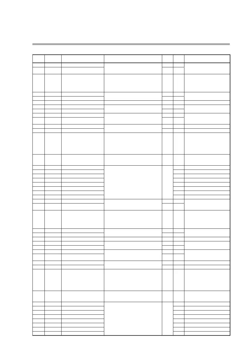
SP configuration bank (Spcnf)
Display
Loop number
(auxiliary display)
Item Settings and descriptions Initial
value
User
setting
Remarks
LMT.0 1 L. 1.
SP low limit -19999 to +32000 U
-1999.9
The decimal point position is
determined by the decimal point
positions for the loop PV/SP.
LMT.02 L. 1.
SP high limit 3200.0
CSP.0 1 L. 1.
SP ramp unit 0: No decimal point/s
1: No decimal point/min
2: No decimal point/h 3: 0.1/s 4: 0.1/min
5: 0.1/h 6: 0.01/s 7: 0.01/min 8: 0.01/h
9: 0.001/s 10: 0.001/min 11: 0.001/h
0
CSP.02 L. 1.
SP ramp-up for LSP 0 U (no ramp) 1 to 32000 U 0 The decimal point position is de-
termined by the SP ramp unit.
CSP.03 L. 1.
SP ramp-down for LSP 0
CSP.04 L. 1.
RSP tracking 0: No tracking 1: Tracking 0
CSP.05 L. 1.
SP ramp-up for RSP 0 U (no ramp) 1 to 32000 U 0 The decimal point position is de-
termined by the SP ramp unit.
CSP.06 L. 1.
SP ramp-down for RSP 0
CSP.07 L. 1.
LSP bias -19999 to +32000U 0 The decimal point position is
determined by the decimal point
positions for the loop PV/SP.
CSP.08 L. 1.
RSP bias 0
CSP.09 L. 1.
PV start for LSP 0: PV start enabled
1: PV start disabled
0
CSP. 10 L. 1.
PV start for RSP 0
CSP. 1 1 L. 1.
Digital RSP selection 0: Disabled
1: Enabled
0 SDC45A/46A/45R/46R
0: When disabled, the PV input
is used as the RSP.
SDC45V/46V
0: When disabled, the RSP
assignment is used as the RSP.
CSP. 12 L. 1.
Digital RSP SP low limit to SP high limit 0 The decimal point position is
determined by the decimal point
positions for the loop PV/SP.
rrA.0 1 L. 1.
RSP ratio 1 0.001 to 32.000 1.000
rrA.02 L. 1.
RSP ratio 2
rrA.03 L. 1.
RSP ratio 3
rrA.04 L. 1.
RSP ratio 4
rrA.05 L. 1.
RSP ratio 5
rrA.06 L. 1.
RSP ratio 6
rrA.07 L. 1.
RSP ratio 7
rrA.08 L. 1.
RSP ratio 8
LMT.0 1 L.2.
SP low limit -19999 to +32000 U
-1999.9
The decimal point position is
determined by the decimal point
positions for the loop PV/SP.
LMT.02 L.2.
SP high limit 3200.0
CSP.0 1 L.2.
SP ramp unit 0: No decimal point/s
1: No decimal point/min
2: No decimal point/h 3: 0.1/s 4: 0.1/min
5: 0.1/h 6: 0.01/s 7: 0.01/min 8: 0.01/h
9: 0.001/s 10: 0.001/min 11: 0.001/h
0
CSP.02 L.2.
SP ramp-up for LSP 0 U (no ramp) 1 to 32000 U 0 The decimal point position is de-
termined by the SP ramp unit.
CSP.03 L.2.
SP ramp-down for LSP 0
CSP.04 L.2.
RSP tracking 0: No tracking 1: Tracking 0
CSP.05 L.2.
SP ramp-up for RSP 0 U (no ramp) 1 to 32000 U 0 The decimal point position is de-
termined by the SP ramp unit.
CSP.06 L.2.
SP ramp-down for RSP 0
CSP.07 L.2.
LSP bias -19999 to +32000U 0 The decimal point position is
determined by the decimal point
positions for the loop PV/SP.
CSP.08 L.2.
RSP bias 0
CSP.09 L.2.
PV start for LSP 0: PV start enabled
1: PV start disabled
0
CSP. 10 L.2.
PV start for RSP 0
CSP. 1 1 L.2.
Digital RSP selection 0: Disabled
1: Enabled
0 SDC45A/46A/45R/46R
0: When disabled, the PV input
is used as the RSP.
SDC45V/46V
0: When disabled, the RSP
assignment is used as the RSP.
CSP.12 L.2.
Digital RSP SP low limit to SP high limit 0 The decimal point position is
determined by the decimal point
positions for the loop PV/SP.
rrA.0 1 L.2.
RSP ratio 1 0.001 to 32.000 1.000
rrA.02 L.2.
RSP ratio 2
rrA.03 L.2.
RSP ratio 3
rrA.04 L.2.
RSP ratio 4
rrA.05 L.2.
RSP ratio 5
rrA.06 L.2.
RSP ratio 6
rrA.07 L.2.
RSP ratio 7
rrA.08 L.2.
RSP ratio 8