0024-9551 Revision 1
16
PCA
®
400 User Manual
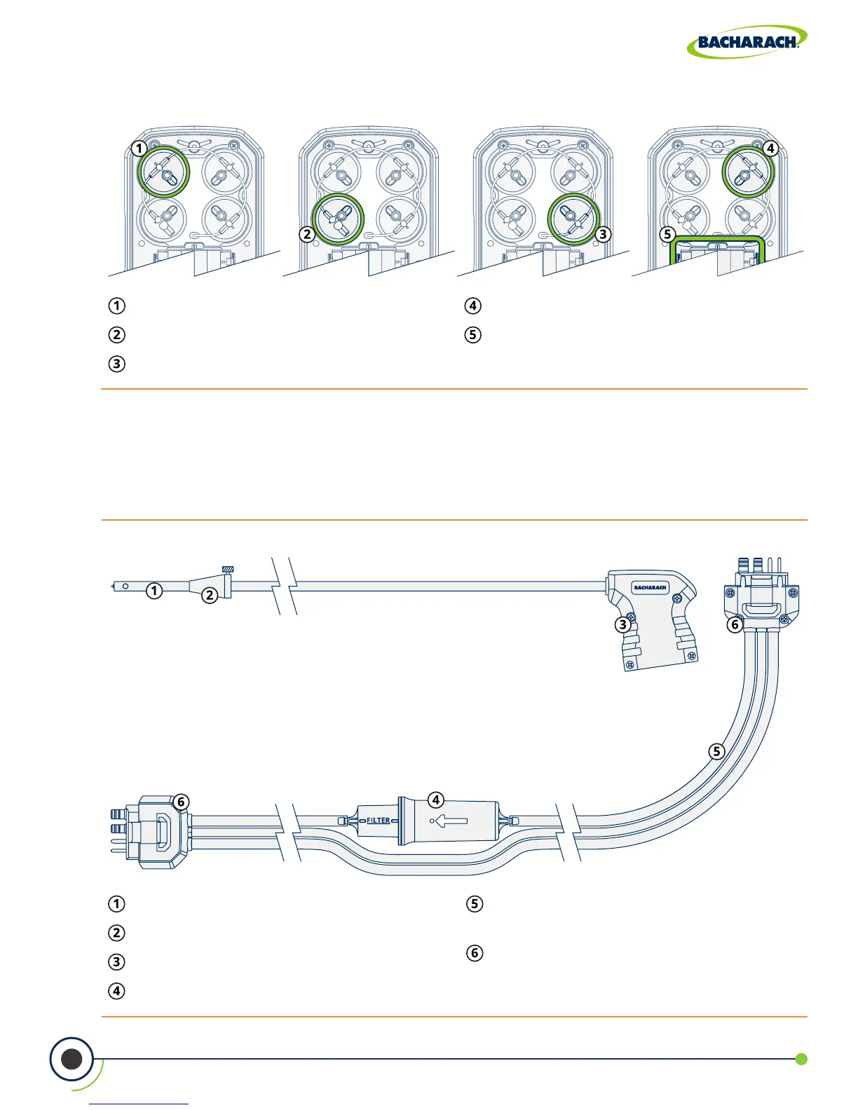
Fig. 2-8: Sensor & Battery Positions
Sensor Position 1 - O
2
Sensor Position 2 - CO
LOW
or CO
HIGH
Sensor Position 3 - NO
2
or SO
2
Sensor Position 4 - NO
Battery Compartment
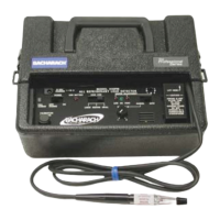
Fig. 2-9: Sample Line & Probe Assembly
Probe Tube - available in multiple lengths.
Probe Stop
Probe Handle
Water Trap / Filter Assembly
Sample Line - available in multiple
lengths and construction types.
Quick-Connector - keyed to t specic
components: gray analyzer, blue probe
handle.
2.2 Sample Line & Probe Assembly
The PCA
®
400’s sample line and probe are modular, allowing users to quickly swap
out dierent sized probe lengths, sample lines and the optional sample conditioner.