Receiving & Installation 3-11
MN1276
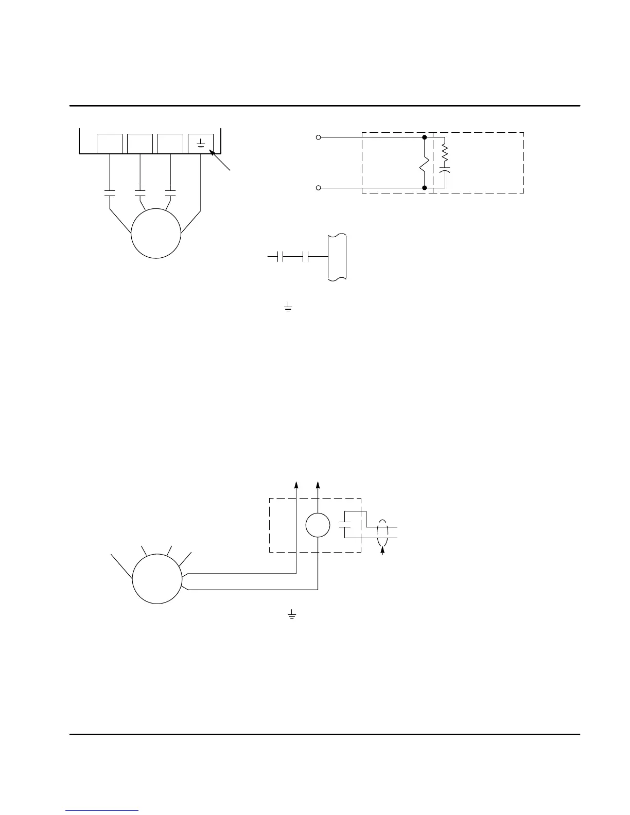
Figure 3-13 Optional M-Contactor Connections
UVW
* RC Device
Electrocube
RG1781-3
U
VW
G
9
*
M Enable
X3
* Motor
MMM
* M-Contactor
To Power Source
(Rated Coil Voltage)
M=Contacts of optional M-Contactor
Note: Close “Enable”
after “M” contact closure.
* Optional components not provided with control.
*
For three phase
controls, this is
labeled “PE”.
Notes:
1. Use same gauge wire for Earth ground as is used for L and N. (VDE (Germany) requires 10mm
2
minimum, 6AWG).
2. For UL installations, connect motor ground to of the control as shown.
For CE installations, connect motor ground to the enclosure backplane (see Figure 3-12).
Note 1
Note 2
Motor Thermostat A relay contact can be used to isolate the motor thermostat leads for use
with other devices, shown in Figure 3-14. The thermostat or overload relay should
be a dry contact type with no power available from the contact. The optional relay
(CR1) shown provides the isolation required and the N.O. contact is open when
power is applied to the relay and the motor is cold. If the motor thermostat is
tripped, CR1 is de-energized and the N.O. contact closes.
Connect the External Trip Input wires (N.O. relay contact) to a PLC or other
device. Note that a machine input may be used and the PLC software of the
Flex+Drive can define the thermal protection. Do not place these wires in the
same conduit as the motor power leads.
Figure 3-14 Motor Temperature Relay
U
V
W
G
* Motor
External Trip
Do not run these wires in same conduit
as motor leads or AC power wiring.
Customer Provided
Source Voltage
Motor Thermostat Leads
CR1
*
*
Optional, customer supplied.
Note: Add appropriately rated protective
device for AC relay (snubber)
or DC relay (diode).
Note 1
Note:
1. For UL installations, connect motor ground to of the control as shown.
For CE installations, connect motor ground to the enclosure backplane (see Figure 3-12).
X1 Dynamic Brake Resistor An external DB (dynamic brake or regen resistor) resistor may be
required to dissipate excess power from the DC bus during motor deceleration
operations. Some controls have an internal resistor. For selection of the DB
resistor, refer to the specifications located in Section 7 and the regeneration
resistor specifications in Section 9 of this manual. DB hardware is connected at
R1 and R2 terminals of the X1 connector, Figure 3-9 and 3-10.
 Loading...
