3-22 Receiving & Installation
MN1276
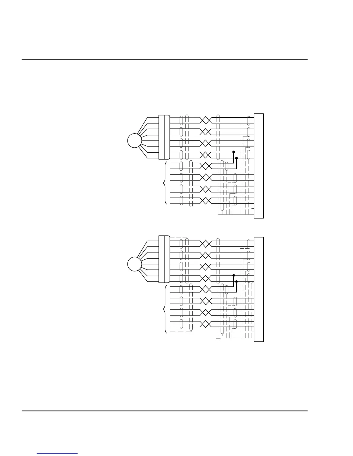
X9 Encoder w/Hall Tracks Optional (Option E)
Twisted pair shielded wire with an overall shield should be used. Figure 3-29
shows the electrical connections between the encoder and the encoder connector.
Figure 3-29 Encoder with Hall Tracks Connections for UL Installations
1
6
2
7
3
8
11
X9
Encoder
4
5
9
14
10
15
13
Shell (Chassis)
Hall 1+
Hall 1--
Hall 3+
Hall 3--
Hall2+
Hall 2--
12 Not Used
Hall
Feedback
A+
A--
B
B+
+5V
DGND
C+
C--
Figure 3-30 Encoder with Hall Tracks Connections for CE Installations
A+
A--
B
B+
+5V
DGND
1
6
2
7
3
8
11
X9
Encoder
C+
C--
4
5
9
14
10
15
13
12
Hall
Feedback
Shell (Chassis)
Hall 1+
Hall 1--
Hall 3+
Hall 3--
Hall2+
Hall 2--
Not Used
 Loading...
