Receiving & Installation 3-19
MN1276
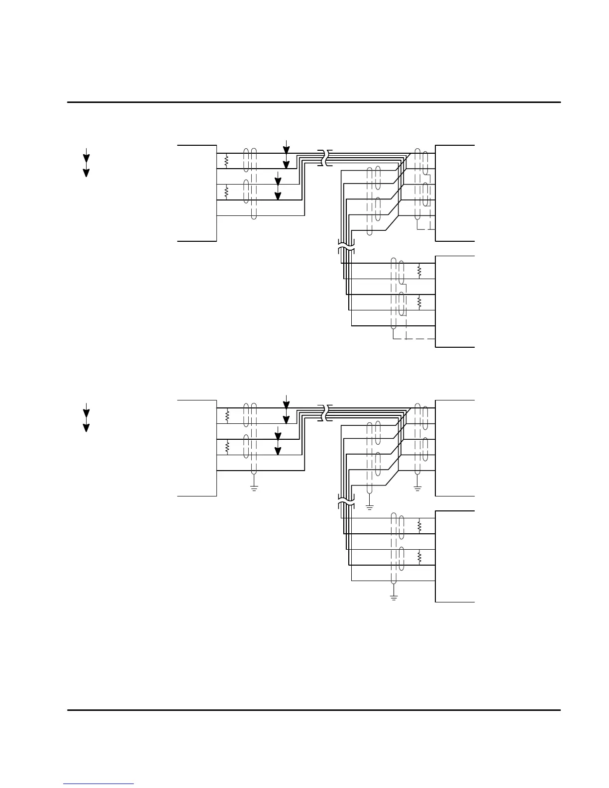
Figure 3-25 RS485 4 Wire Multi-Drop for UL Installations
* Terminating resistor T
R
is 120 W typical value.
Only the PC and last control are terminated.
TX+
TX--
X6
Host
Computer
DGND
GND
TX+
TX--
Shields
DGND
GND
*
RX+
RX--
DGND
GND
T
R
*
T
R
TX+
TX-
RX+
RX-
RX+
RX-
Use twisted pair shielded cable
with an overall shield.
P
=TwistedPair
P
P
X6
Shields
*
T
R
*
T
R
Figure 3-26 RS485 4 Wire Multi-Drop for CE Installations
* Terminating resistor T
R
is 120 W typical value.
Only the PC and last control are terminated.
TX+
TX--
X6
Host
Computer
DGND
GND
TX+
TX--
DGND
GND
*
RX+
RX--
DGND
GND
T
R
*
T
R
TX+
TX-
RX+
RX-
RX+
RX-
Use twisted pair shielded cable
with an overall shield.
P
=TwistedPair
P
P
X6
PE
PE
PE
PE
*
T
R
*
T
R
Note: For CE installations, connect the overall shield at each end of the cable to PE. The
voltage potential between the PE points at each end of the cable must be Zero Volts.
See Section 4 of this manual for the description of switch “AS1-1 to AS1-4” for
address settings for multi-drop applications.
 Loading...
