A-6 Manual Tuning
MN1276
POLE
PLACEMENT
Pole placement provides a “no--overshoot response” when tuned for the correct
inertia. This is the easiest and recommended method of adjustment.
Inertia Click in the “Load” block and enter the value in Kg--cm
2
. The range is from
0to133Kg--cm
2
.
If the inertia is under--estimated, the system will be stable. If the inertia is
over--estimated, the system will vibrate or oscillate due to too much system gain.
If the load inertia is unknown, estimate low. It is recommended to start with “load
inertia = 0.2”, which represents a stable condition.
If you entered the “inertia ratio”, you should enter a value representing the ratio of
reflected load inertia to motor inertia. The range is from 0 to 100.
Response Move to the “Response” block and place the cursor in the “bandwidth” window,
and click on it.
The “bandwidth” is a measure of the range over which the system can respond. It
is expressed in frequency or Hertz. This parameter controls the “rise time” of the
system. It does not effect overshoot.
It is recommended that bandwidth is increased only if higher dynamic response is
required. Increase the bandwidth and observe (go to plotting of move) the
“velocity” and “command current”, until current reaches maximum value, then back
off to 80%. The range is from 10--200.
The next step, would be to verify that the v alue you entered, provides for adequate
system response. You can check this out, by having the software move the
equipment and plot the response. Proceed to “Plotting of Move”.
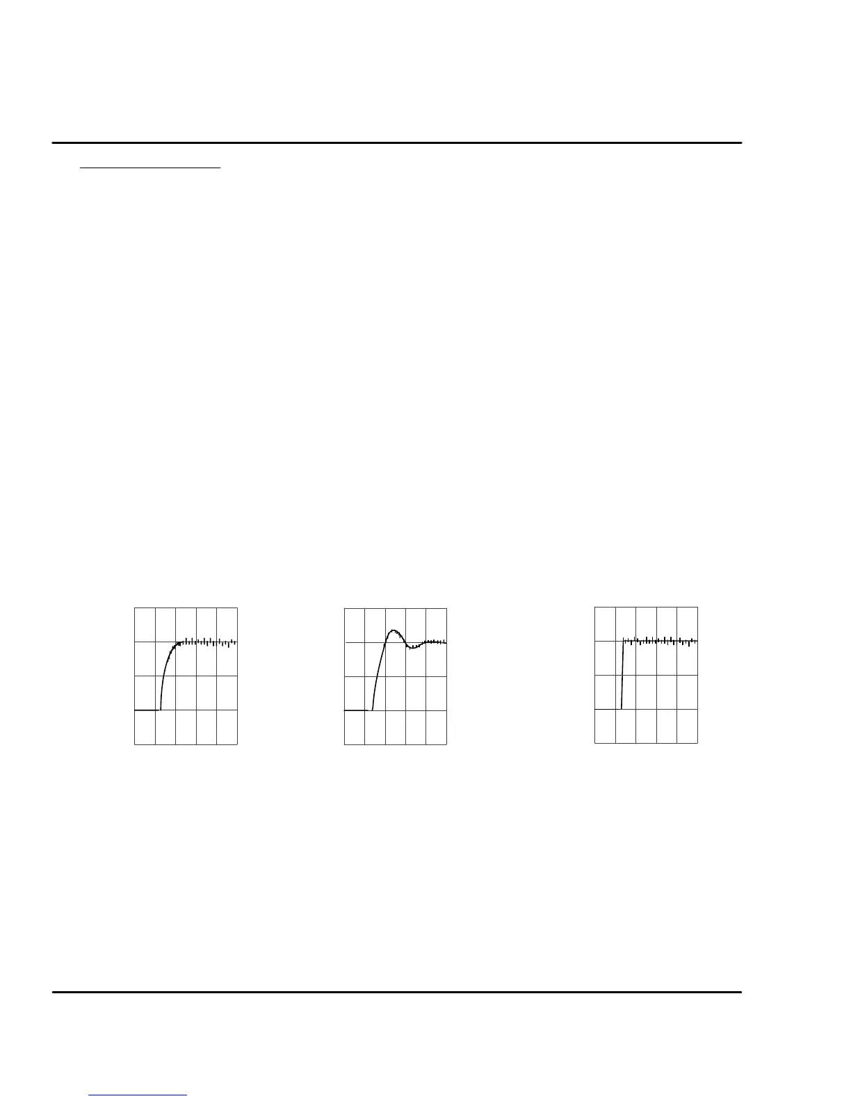
Figure A-10 Inertia and Load Response Examples
Velocity (RPM)
Time
Velocity Command / Velocity
--500
0
500
1000
1500
Velocity (RPM)
Time
Velocity Command / Velocity
-- 5 0 0
0
500
1000
1500
Over--Estimated Under--Estimated
Velocity (RPM)
Time
Velocity Command / Velocity
-- 5 0 0
0
500
1000
1500
Good Response
Tracking factor
The tracking factor parameter controls the amount of tracking versus overshoot.
The range is 0 to 200. A “tracking factor” of “0” generates no overshoot. A
“tracking factor” of 200 results in a PI equivalent control (i.e. with overshoot).
The next step, would be to verify that the v alues you entered, provides for
adequate system response. You can check this out, by having the software move
the equipment and plot the response. Proceed to “Plotting of Move”.
Click in the “Tracking” block and enter the desired adjustment value. This
adjustment is used for applications that require improved tracking (or following)
capability, to improve (or reduce) following error.
 Loading...
