46
1.9.3.1.2 12-pin Wire-to-Board header (Dig I/O) Manufacturer: JST
Part number: B12B-PH-K
Attention
"False tensions or short-circuits"
The digital I/O's are connected directly via a resistor to the FPGA pins and therefore they are not
protected. If you connect the digital I/Os without providing a protection you will risk damaging the device.
→ - Provide a protection circuit to the digital I/O's of mvBlueFOX-M. - Afterwards connect the digi-
tal I/Os to the FPGA pins.
See also
High-Speed USB design guidelines (p. 10)
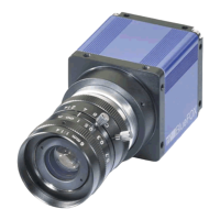
1.9.3.1.3 Contact
Figure 13: Contact, dimensions in mm (in.)
Application wire Q'ty / reel
mm2 AWG # Insulation O.D. mm (in.)
0.05 to 0.22 30 to 24 0.9 to 1.5 (.035 to .059) 8.000
Material and finish: phosphor bronze, tin-plated
Manufacturer: JST
Part number: SPH-002T-P0.5S
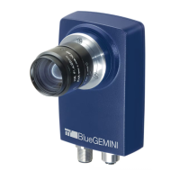
1.9.3.1.4 Housing
Figure 14: Housing, dimensions in mm (in.)
MATRIX VISION GmbH