12. Convergence
Convergence test pattern
4
1
2
5
3
6
3
6
2
5
4
1
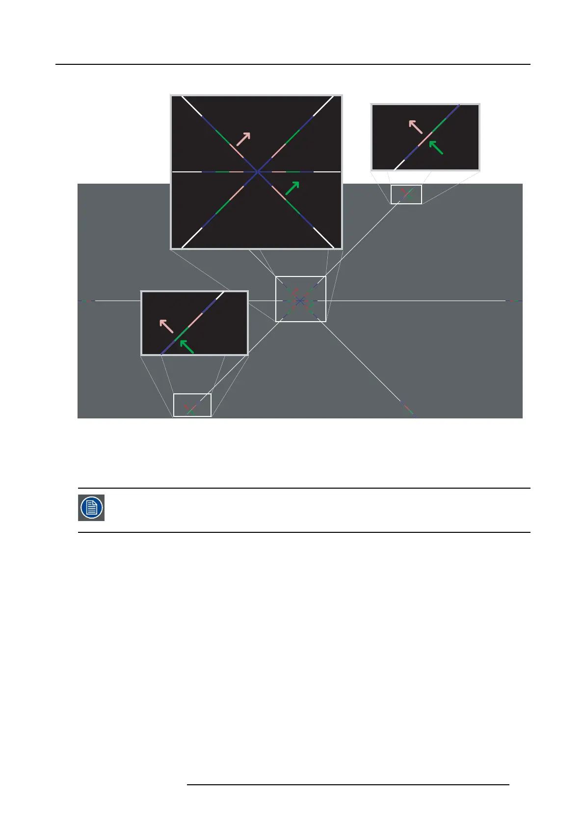
Image 12-2
Convergence test pattern
The test pattern illustrated above is sp ecially designed for convergence purp oses. The test pattern has three red arrows numbered
from 1 to 3 and three green arrows num bered from 4 to 6. These numb ers and colors c orrespond w ith the number s and colors of
the e xtended control kn obs (image 12-1). T he direction of the arrow shows the m ovem ent of the c hannel color (red or green) when
turning the corresponding k nob in the direction indicated by the arrow m arked on the kno b.
The three convergence control knob
s of one chan nel stand in relation with each other. So, a ch ange to on e
of them will also effect the adjustment results of the two others. Therefore, all three control knobs have to
be alternately and repeatedly ad justed until the projected color is perfectly converged with the blue reference
color of the test pattern.
Adjustment range
• The adjustment range is limited to approximately 30 pixels in both directions.
• One turn (360°) of a c ontrol knob relates to an approximately 30 pixel displacement on the screen.
• When changing the adjustment d irection there w ill be some play of approximately one turn (360°).
R59770351 DP2K-20C 02/02/2010
117

 Loading...


