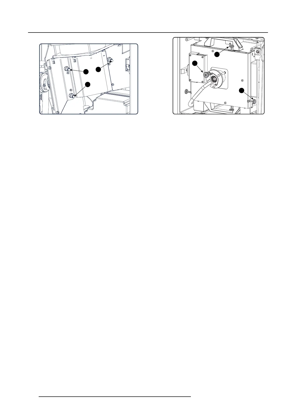
7. Cold mirror assembly
Z
X
Y
3
1
2
Image 7-12
2. Tu rn the adjus tment screw 3 (reference 3 image 7-12) in or out until the m axim um light output is mea sured.
3. Repeat step 1 and 2 until the m aximum light output is measured.
4. Adjust the X-axis, Y-axis and Z-axis (reference X, Y & Z im age 7-12) of the xenon lamp in the Lamp House for maximum light
output. C arefully turn the thumbscrew for maximum light output. Once over the maximum, turn slightly in opposite direction to
reach the ma ximum light output again. Do this for each direction and minimu m repeat t his adjustment cy cle twice.
5. Turn the adjustment screw 1, 2 and 3 (reference 1, 2 & 3 image 7-12) equally in or out until the maximum light output is measured.
6. Repeat from s tep 1 until the maximum light o utput is measured.
7. Check the brightness uniformity. In most cases it will be OK.
If not OK, turn slightly on the adjustment screws 2 and 3 (reference 2 & 3 ima ge 7-12) until a uniform brightness is obtained.
- Screw 2 (reference 2 image 7-12) will correct the difference between the left and the right side of the pr ojected im age.
- Screw 3 (reference 3 image 7-12) will correct the difference between the top and the bo ttom side of the projected im age.
Check again and repea t if nece ssary.
8. When the adjustmen t is finished, secure the position of t he c old mirror by turning the lock nuts ( reference 4 image 7-12) against
the plate (hold on the screws while securing the nuts).
132
R5905043 DP2K-12C/11CX 19/02/2018

 Loading...


