5. Physical installation
E
D
F
G
B
L2
L3
L1
N
A1 A2 A3
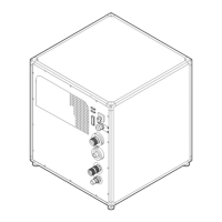
Image 5-21
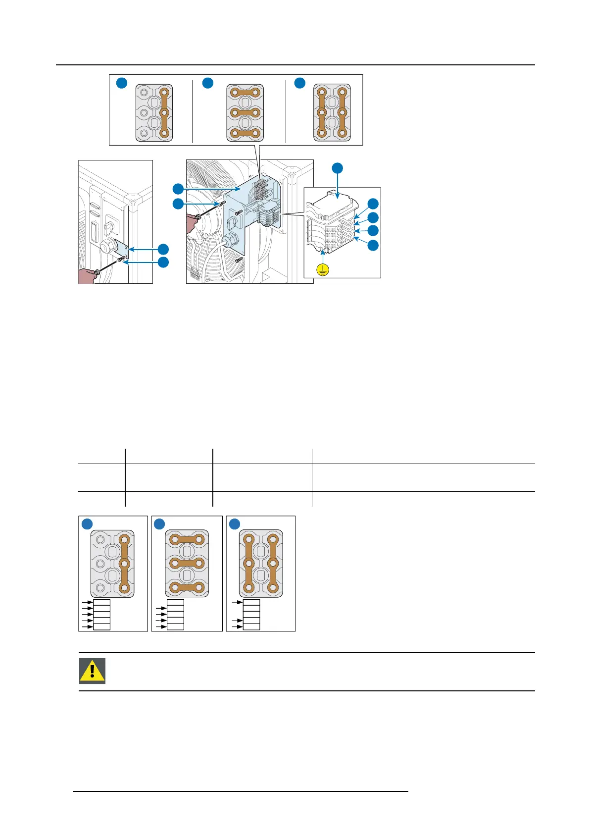
2. Remov e the small plate (D).
3. Unscrew the screws (F).
4. Slide out the support (G).
5. Set up the terminal box according to voltage and power frequency (see wiring diagrams A1, A2, A3).
6. Connect the power feed cable to t he terminal box (B) as indicated in t he table “Terminal box and cable connection layout diagra m”.
7. Insert the support (G).
8. Tighten the screws (F).
9. Put the small plate (D ) in place.
10.Tighten the screws (E).
Terminal box and ca ble connection layout diagram
A1 350 - 400 V 3~ L1 - L2 - L3 - N - PE
Star connection - 4 pole cable + ground
A2 200 - 240 V 3~ L1 - L2 - L3 - PE Delta connection - 3 pole cable + ground
CAUTION! Do not connect the neutral pole
A3 200 - 240 V 1~ L1 - N - PE
Single-phase connection - 2 pole c able + ground
N
U1
V1
W1
W2
U2
V2
U1
V1
W1
W2
U2
V2
U1
V1
W1
W2
U2
V2
L3
L2
L1
PE
230 / 400V
3W+N+PE
16A
50-60 Hz
208V
3W+PE
16A
50-60 Hz
230V
1W+N+PE
22A
50-60 Hz
N
L3
L2
L1
PE
N
L3
L2
L1
PE
A1 A2 A3
Image 5-22
CAUTION: L1, L2, L3 and the N w ire are all black wires. Be careful when connecting the wiring that you do
not sw itc h the N wire with any of the L w i r es.
26 R5905866 ULC-30A 31/01/2018