5. Physical installation
2
1
A
B
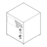
Image 5-32
5.8 Connecting the hoses with projector and chillers
What has to be done?
The cooling circuit of the chiller(s) has to be conn ected with the cooling circuit of the pro jector. For that hoses are needed. The
length of the hoses depend on the po sition of the chillers in relation to the pr ojector. The maximum length is 10 m eter!
The method of connec ting the pro jector with the chillers depends on the type of projector the chiller will be connected to. For prop er
connection instructions with your projector, refer to the projector ins tallation m anual.
It is also advised to use the correct accessory kit to install the support fram es before you connect the hoses
and use the hose shells after connecting the h oses. See t he Accessory kit installation manual for more d etails.
General hoses IN/OUT connection scheme
The labels on the projector and on the chillers indicate the three possible cooling circuits: (R/B, G and DM D) and the direction of the
liquid flow: OUT and IN. ’OUT’ m eans liquid flo w s out of the chiller or projector, ’IN’ means liquid flow s into the chiller or project or.
Both sides of all hoses are also labeled.
Chiller without DMD cooling unit Chiller with DMD cooling unit Connected projector
DMD OUT
DMD IN
DMD IN
DMD OUT
R/B OUT R/B IN
GOUT GIN
GIN GOUT
R/B IN R/B OUT
CAUTION: Do not interchange the different cooling circuits with each o ther! O therw ise the system w ill fail.
30 R5905866 ULC-30A 31/01/2018