25-2 9424200996
Virtual Control Switches (43) BE1-11m
(logic 1) and enable it when the switch is open (logic 0). For the application, you may set the switch label
to be 59N CUTOFF. The closed position of the switch may be labeled DISABLD and the open position
may be labeled NORMAL.
Control of Virtual Control Switches
The state of the virtual control switches can be controlled using the Select/Operate Control Switch buttons
on the front panel or through BESTCOMSPlus when the connection state is active. Using select-before-
operate, perform the following steps to control a switch using BESTCOMSPlus:
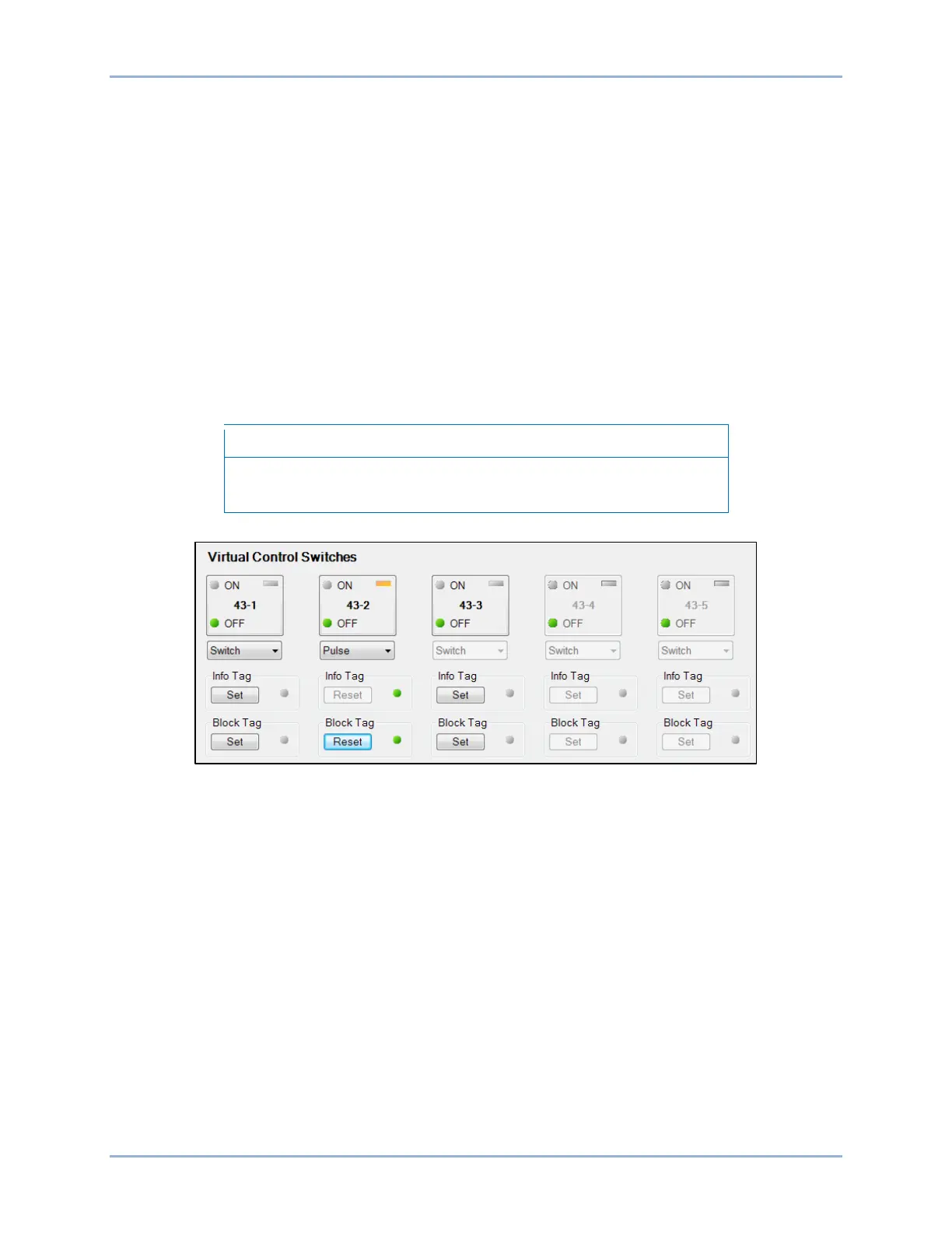
1. Use the Metering Explorer to open the Control/Virtual Switches tree branch (Figure 25-1).
2. If Switch/Pulse mode is selected on the Virtual Control Switches (43) settings screen in
BESTCOMSPlus, use the drop-down box to select either Switch or Pulse.
3. Click the 43-# button to select it. Login may be required. The On or Off indicator (current state)
will begin to flash.
4. Click on the 43-# button a second time to operate it. The On or Off indicator (previous state) will
stop flashing and the Off or On indicator (current/new state) will light.
If Step 4 is not performed within 30 seconds of Step 3, the LED will
stop flashing and the 43-# button will have to be selected again.
Figure 25-1. Virtual Switches Control Screen
Tagging of Virtual Control Switches
Virtual control switches provide tagging for each switch to indicate that the switch function is, or may be,
under revision. Each switch has two tagging modes, Informational and Blocking. When in Informational
mode, the switch is still operational when tagged. When in the Blocking mode, the switch is not
operational when tagged.
Tagging of virtual control switches can be accomplished through the front panel and through
BESTCOMSPlus. Use the Metering Explorer in BESTCOMSPlus to open the Control/Virtual Switches tree
branch. Click on the Set button for Info Tag or Block Tag. If tagging is successful, the indicator to the right
of the Set button will turn green. A tagged switch is indicated by an amber indicator in the upper right
corner of the element button. Click on the Reset button to clear a tag. Refer to Figure 25-1.
The Block Tag has priority over the Informational Tag. Once the Block Tag has been placed, the
Informational Tag cannot be changed until the Block Tag is removed. In other words, you must choose to
place the Informational Tag before placing the Block Tag.
Each tag is placed with an “owner”. A tag must be removed by the same “owner” that placed it. For
example, if a tag is placed through BESTCOMSPlus, it can be removed only through BESTCOMSPlus. It
cannot be removed through the front panel. If a tag is placed through the front panel, it can be removed
only through the front panel. This applies for all other forms of communication when placing tags.