48-2 9424200996
BESTlogic™Plus BE1-11m
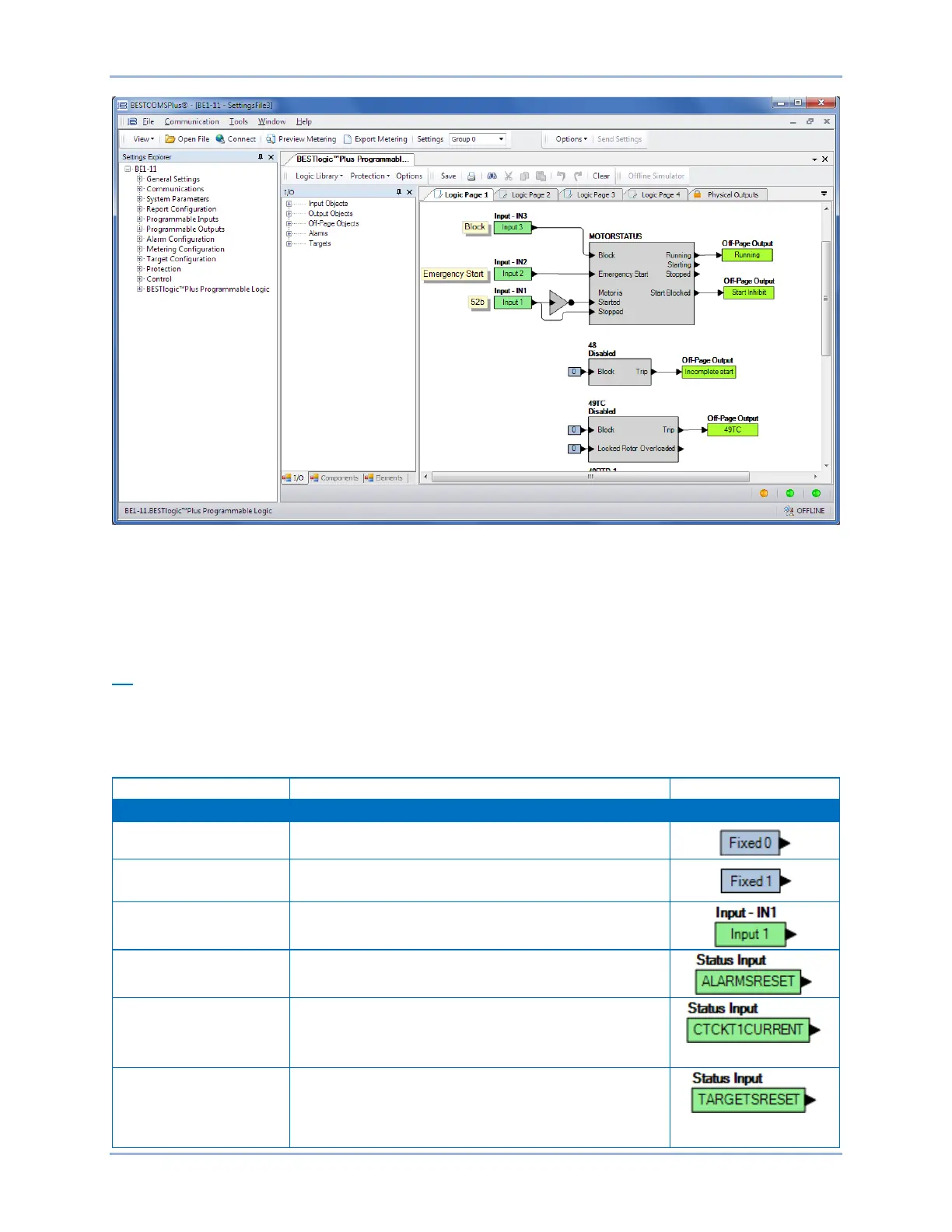
Figure 48-1. BESTlogicPlus Programmable Logic Tree Branch
BESTlogic™Plus Composition
There are three main groups of objects used for programming BESTlogicPlus. These groups are I/O,
Components, and Elements. For details on how these objects are used to program BESTlogicPlus, see
the paragraphs on Programming BESTlogicPlus.
I/O
This group contains Input Objects, Output Objects, Off-Page Objects, and Alarms. Input objects can be
logically connected to any logic block input. Output objects can be logically connected to any logic block
output. Table 48-1 lists the names and descriptions of the objects in the I/O group.
Table 48-1. I/O Group, Names and Descriptions
Always false (Low). Double-click or right-click on the
object to change the fixed state from 0 to 1.
Always true (High). Double-click or right-click on the object
to change the fixed state from 1 to 0.
IN1 – IN10
True when Physical Input x is active.
Alarm Reset
The Alarm Reset status input goes momentarily high
when the Major, Minor, and Logic alarms are cleared.
CT Circuit 1 and CT
Circuit 2 Current
The CT Circuit 1 Current Detected status input goes high
when ac current is greater than 5% of nominal as
determined by the fast current detector.
Target Reset
The Target Reset status input goes momentarily high
when the targets are cleared.