9424200996 61-3
BE1-11m Frequency (81) Test
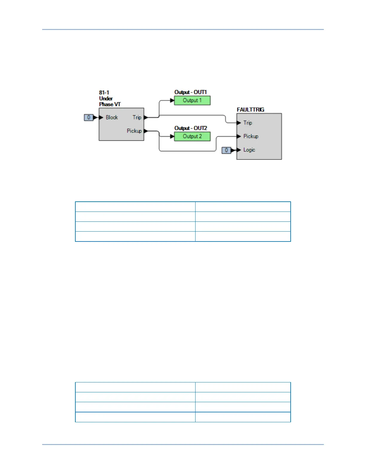
Step 2: Use BESTCOMSPlus to configure the BESTlogicPlus programmable logic shown in Figure
61-2.
• Blocking is disabled.
• OUT1 closes for 81-1 Trip.
• OUT2 closes for 81-1 Pickup.
• Fault recording is enabled.
Figure 61-2. BESTlogicPlus Settings (Underfrequency)
Step 3: Use BESTCOMSPlus to open the Protection, Frequency, Frequency (81-1) screen and send
the first row of test settings in Table 61-4 to the BE1-11m.
Table 61-4. Pickup Test Settings (Underfrequency)
Step 4: Prepare to monitor the 81-1 function operation. Operation can be verified by monitoring OUT2
(see Figure 61-2).
Step 5: Connect and apply a 120 Vac, 60-hertz voltage source to terminals C13 (A-phase) and C16
(neutral).
Step 6: Slowly decrease the frequency of the applied voltage until OUT2 closes and record the pickup.
Verify that there is an 81-1-Under target on the front-panel display. Slowly increase the
frequency until OUT2 opens and record the dropout.
Step 7: Repeat step 6 for the 46 Hz and 48 Hz pickup settings listed in Table 61-4. Record the results.
Step 8: (Optional.) Repeat steps 1 through 7 for settings groups 1, 2, and 3.
Step 9: (Optional.) Repeat steps 1 through 8 for 81-2, 81-3, and 81-4.
Time Delay Verification
Step 1: Use BESTCOMSPlus to open the Protection, Frequency, Frequency (81-1) screen and send
the first row of test settings in Table 61-5 to the BE1-11m. Commands entered in Table 61-3
should be retained for this test.
Table 61-5. Timing Test Settings
Step 2: Prepare to monitor the 81-1 timings. Timing accuracy is verified by measuring the elapsed time
between a frequency change and OUT1 closing.