65-6 9424200996
Inverse Overcurrent (51) Test BE1-11m
Pickup Verification (I2 Mode)
Step 1: Use BESTCOMSPlus to send the operational settings in Table 65-9 to the BE1-11m. Reset all
targets.
Table 65-9. Operational Settings (I2 Mode)
System Parameters, Sensing
Transformers
Protection, Current, Instantaneous
Overcurrent (51-1)
Enables 51-1 function for I2
mode
Protection, Current, Instantaneous
Overcurrent (51-1)
Selects CT circuit 1 as the
source
Target Configuration, Targets
Enables Neg SEQ target
for 51-1
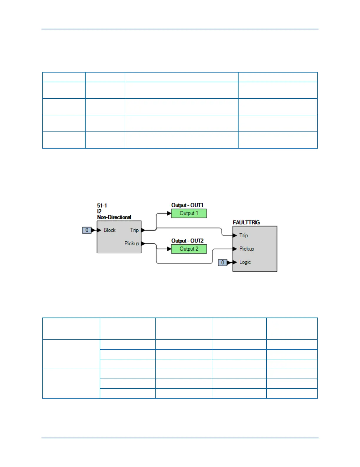
Step 2: Use BESTCOMSPlus to configure the BESTlogicPlus programmable logic shown in Figure
65-3.
• Blocking is disabled.
• OUT1 closes for 51-1 Trip.
• OUT2 closes for 51-1 Pickup.
• Fault recording is enabled.
Figure 65-3. BESTlogicPlus Settings (I2 Mode)
Step 3: Use BESTCOMSPlus to open the Protection, Current, Inverse Overcurrent (51-1) screen and
send the low range test settings (minimum pickup setting) to the BE1-11m for your sensing input
type in Table 65-10.
Table 65-10. Pickup Test Settings (I2 Mode)
Sensing Input
Type
Range Pickup Setting Time Dial Time Curve
5 A
1 A
Step 4: Prepare to monitor the 51-1 function operation. Operation can be verified by monitoring OUT2
(see Figure 65-3).
Step 5: Connect a current source to terminals D1 and D2 (A-phase). For a single-phase input test, I2 =
Ia / 3. Therefore, the BE1-11m should pick up at a value of three times the setting value when