67-4 9424200996
Power (32) Test BE1-11m
Step 6: (Optional.) Repeat steps 1 through 5 for B-phase and C-phase currents. (Consult the Power
(32) Protection chapter for operating details.)
Step 7: (Optional.) Repeat steps 1 through 6 for settings group 1, 2, and 3.
Step 8: (Optional.) Repeat steps 1 through 7 with CT2 as the bus CT selection for protection systems
equipped with two sets of CTs. In step 2, replace D1 with F1, D2 with F2, etc.
Reverse Tripping Direction (Underpower)
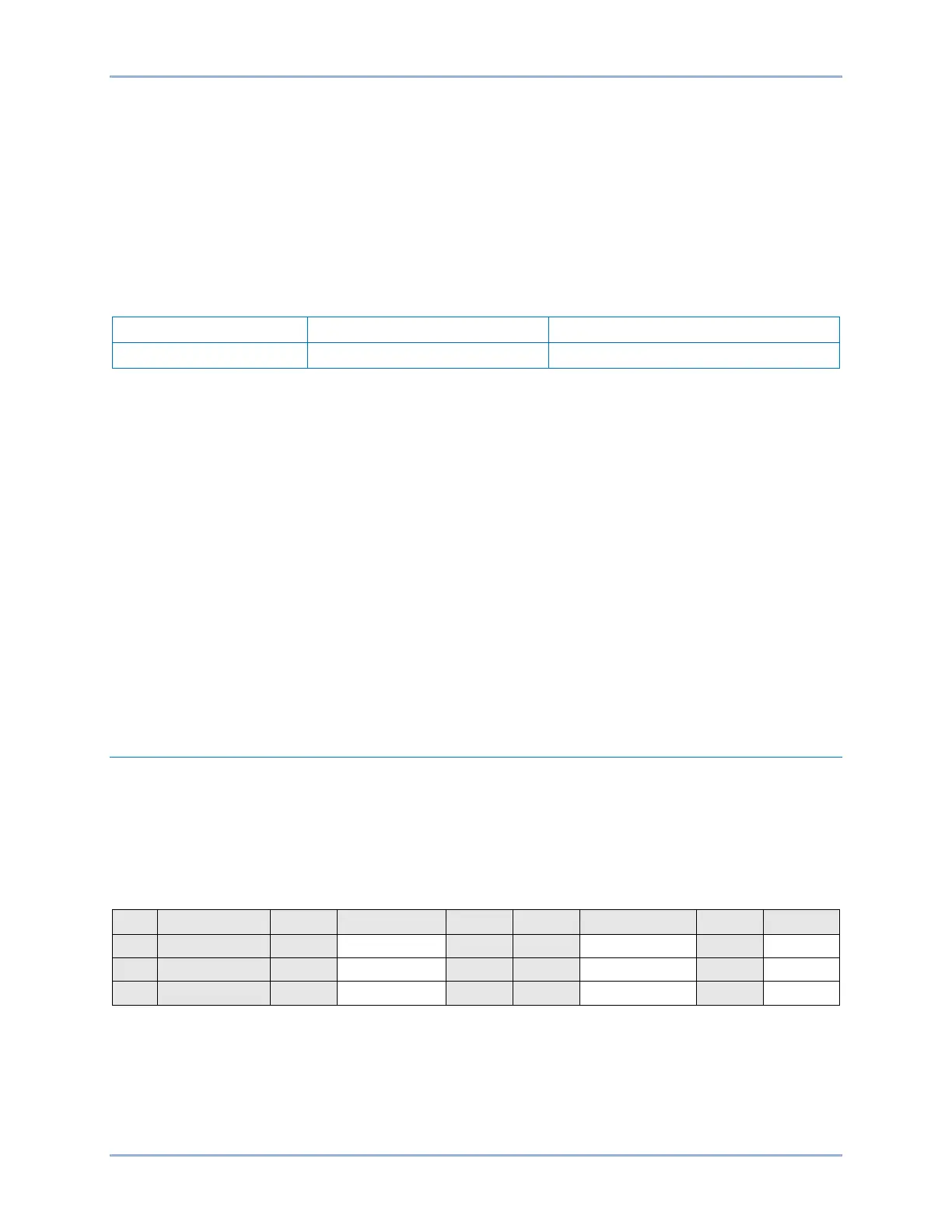
Step 1: Using Table 67-5 as a guide, send the 32-1 settings to the BE1-11m. Prior to each test, reset
the BE1-11m targets from the previous test.
Table 67-5. Reverse-Underpower Test Settings
Step 2: Connect and apply a 100 Vac, three-phase voltage source at nominal frequency to terminals
C13 (A-phase), C14 (B-phase), C15 (C-phase), and C16 (neutral). Connect a variable ac
current source to terminals D1 (A-phase polarity) and D2 (A-phase non-polarity).
Step 3: Apply 4 amps A-phase current to lag the voltage by 180 degrees noting that OUT2 drops out.
Slowly decrease the current until OUT2 closes and record the pickup. Verify that there is a 32-1-
A-Under target on the front-panel display. Increase A-phase current until OUT2 opens and
record the reset. Pickup will occur within ±3% of the 32-1 pickup setting (500 watts = 5 amps,
100 volts, 180 degrees I lag E).
Step 4: With the BE1-11m picked up (OUT2 closed), change the angle of the applied current so that it’s
in phase with the voltage and verify that OUT2 opens. This verifies that the 32-1 function is
operating in the reverse trip direction and not in the forward direction.
Step 5: (Optional.) Repeat steps 1 through 4 for B-phase and C-phase currents. (Consult the Power
(32) Protection chapter for operating details.)
Step 6: (Optional.) Repeat steps 1 through 5 for settings group 1, 2, and 3.
Step 7: (Optional.) Repeat steps 1 through 6 with CT2 as the bus CT selection for protection systems
equipped with two sets of CTs. In step 2, replace D1 with F1, D2 with F2, etc.
Functional Test Report
Forward Tripping Direction (Overpower)
Pickup Setting Range = 1 to 6,000 Watts for 5A sensing
1 to 1,200 Watts for 1A sensing
Pickup Accuracy = ±3 or ±2 W, whichever is greater
Dropout should occur between 95-99% of the actual pickup value.
* Dropout range is calculated from the pickup setting and may need adjusted based on actual pickup.