69-2 9424200996
Power Factor (55) Test BE1-11m
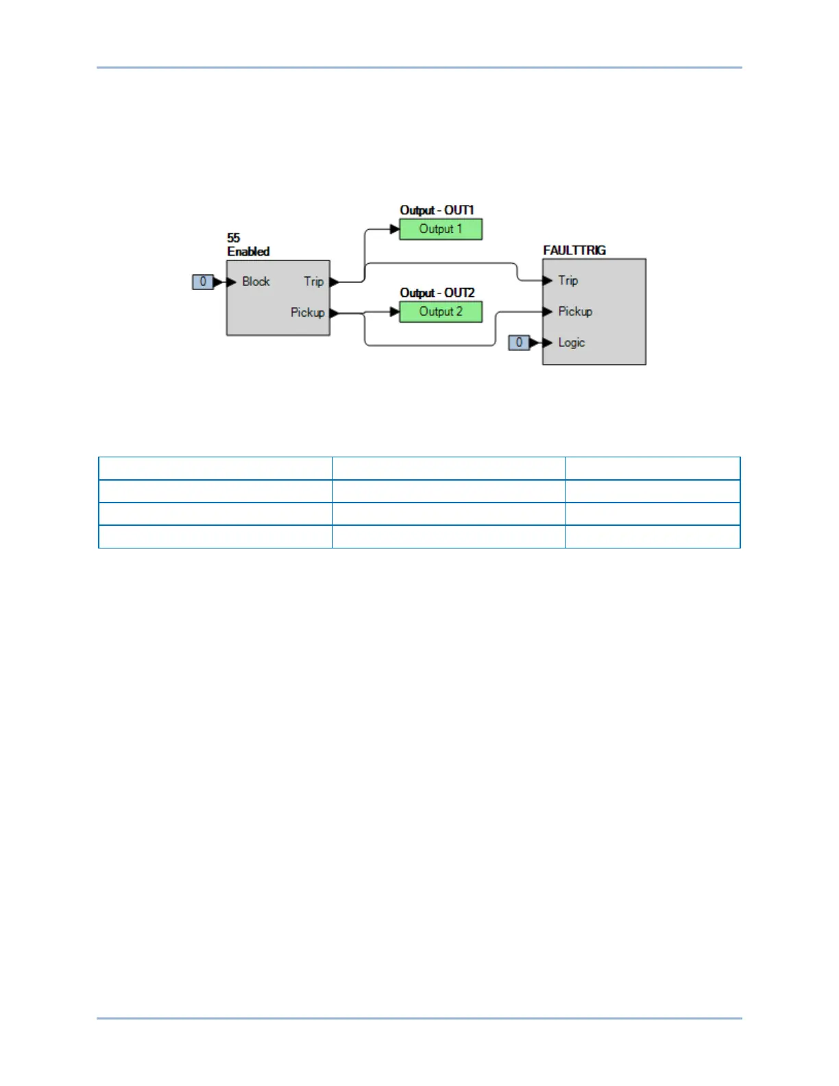
Step 2: Use BESTCOMSPlus to configure the BESTlogicPlus programmable logic shown in Figure
69-1.
• Blocking is disabled.
• OUT1 closes for 55 Trip.
• OUT2 closes for 55 Pickup.
• Fault recording is enabled.
Figure 69-1. BESTlogicPlus Settings
Step 3: Use BESTCOMSPlus to open the Protection, Power, Power Factor (55) screen and verify the
first row of test settings in Table 69-2 to the BE1-11m.
Table 69-2. Pickup Test Settings
Step 4: Prepare to monitor the 55 function operation. Operation can be verified by monitoring OUT1
(see Figure 69-1).
Step 5: Connect and apply 5 A∠0° to terminals D1 (A-phase polarity) and D2 (A-phase non-polarity)
and a three-phase 69.28 V phase-neutral voltage source to terminals C13 (A-phase), C14 (B-
phase), C15 (C-phase), and C16 (Neutral).
Step 6: Rotate the IA angle in the leading direction until a pickup occurs. This should happen at ∠IA =
∠VA + cos
-1
(0.5) = +60° ±0.66° (0.49 – 0.51 PF leading). Decrease the IA angle until OUT1
opens and record the reset. Reset the target.
Step 7: Rotate the IA angle in the lagging direction until a pickup occurs. This should happen at ∠IA =
∠VA – cos
-1
(0.5) = –60° ±0.66° (0.49 – 0.51 PF lagging). Increase the IA angle until OUT1
opens and record the reset. Reset the target.
Step 8: Verify the pickup accuracy and reset for settings as listed in Table 69-2. Record the results.
Pickup accuracy is ±0.01 PF or equivalently ±|cos
-1
(pickup) – cos
-1
(pickup ±0.001)|° of the
associated angle.
Step 9: (Optional.) Repeat steps 1 through 8 for the B-phase and C-phase current inputs taking into
consideration the different current angles. Note: Be sure to enable proper target for each phase
being tested.
Step 10: (Optional.) Repeat steps 1 through 9 for settings group 1, 2, and 3.
Timing Verification
Step 1: Use BESTCOMSPlus to open the Protection, Power, Power Factor (55) screen and send the
first row of test settings in Table 2 for settings group 0.
Step 2: Prepare to monitor the 55 timings. Timing accuracy is verified by measuring the elapsed time
between a sensing voltage change and OUT1 closing.