9424200996 4-5
BE1-11m Contact Inputs and Outputs
1. The relay trouble alarm disables all hardware outputs.
2. The programmable hold timer is active.
3. The select-before-operate function overrides a virtual output.
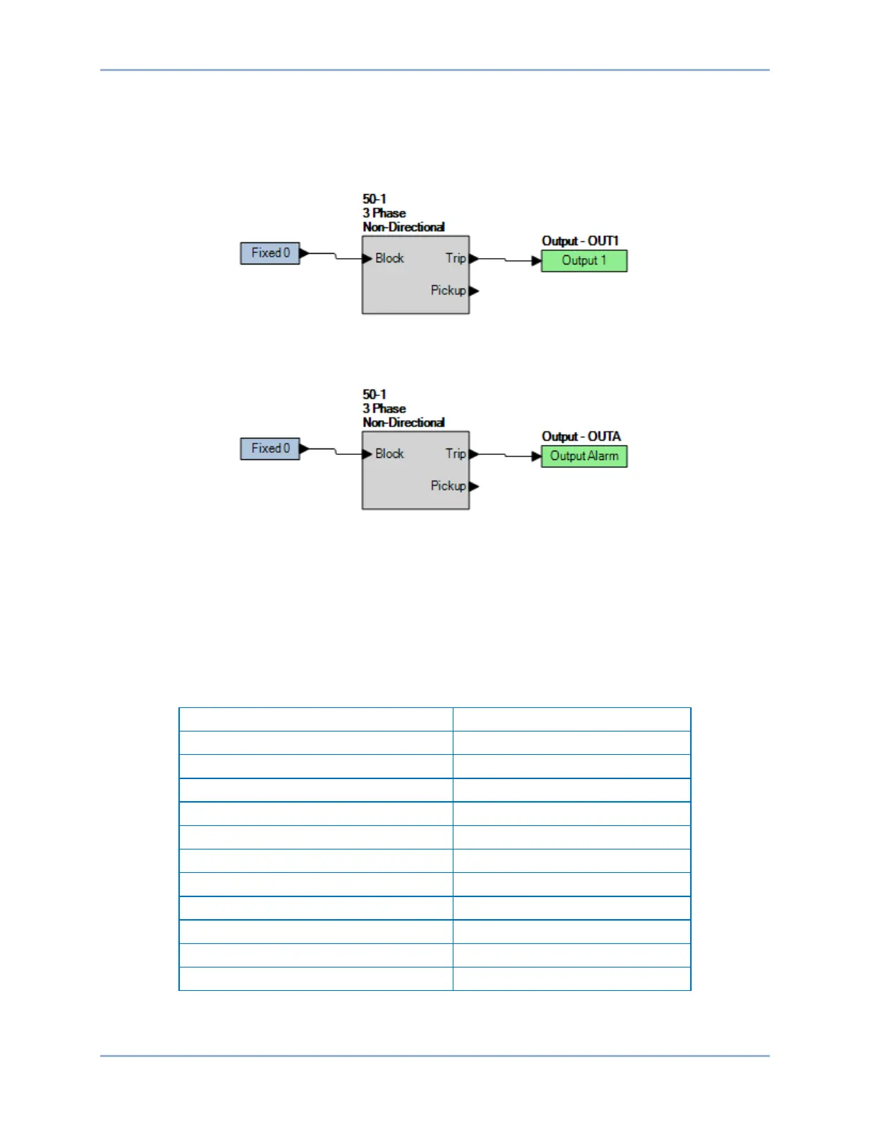
Figure 4-4 shows a diagram of the contact output logic for the general-purpose contact outputs. The
OUT1 relay closes when the 50-1 element is in a trip condition.
Figure 4-4. Output Logic, General Purpose Contact Outputs
Figure 4-5 illustrates the contact output logic for the failsafe alarm contact output when OUTA is normally
closed (style xxxxxxx2xxxxxx). The OUTA relay closes when the 50-1 element is in a trip condition.
Figure 4-5. Output Logic, Failsafe Alarm Contact Output
Relay Trouble Alarm Disable
All internal circuitry and software that affects how the BE1-11m functions is monitored by the continuous
self-test diagnostics function of the relay trouble alarms. A detailed list of relay trouble alarms is provided
in Table 4-3. If any one of these points asserts, the failsafe alarm output relay de-energizes and
closes/opens (depending on style number) the OUTA contact, the front-panel Relay Trouble LED lights,
all output relays are disabled, logic OUTA is set, and the BE1-11m is taken offline. The relay trouble
alarms function is not programmable.
Table 4-3. Relay Trouble Alarms
NVMH Settings File Not Opened
Error opening settings file
Error writing settings file
Error writing settings file
Error writing settings file
Defaults have been loaded
Input power is too low/failed