4-6 9424200996
Contact Inputs and Outputs BE1-11m
Programmable Hold Timer—Hold Attribute
Historically, electromechanical relays have provided trip contact seal-in circuits. These seal-in circuits
consisted of a dc coil in series with the relay trip contact and a seal-in contact in parallel with the trip
contact. The seal-in feature serves several purposes for electromechanical relays. One purpose is to
provide mechanical energy to drop the target. A second purpose is to carry the dc tripping current from
the induction disk contact, which might not have significant closing torque for a low resistance connection.
A third purpose is to prevent the relay contact from dropping out until the current has been interrupted by
the 52a contacts in series with the trip coil. If the tripping contact opens before the dc current is
interrupted, the contact might be damaged. Of the three items, only item three is an issue for electronic
protection systems like the BE1-11m.
Contact Output Seal-In Logic
To prevent the output relay contacts from opening prematurely, a hold timer (200 to 2,000 ms) can be set
with BESTCOMSPlus. If the protection engineer desires seal-in logic with feedback from the breaker
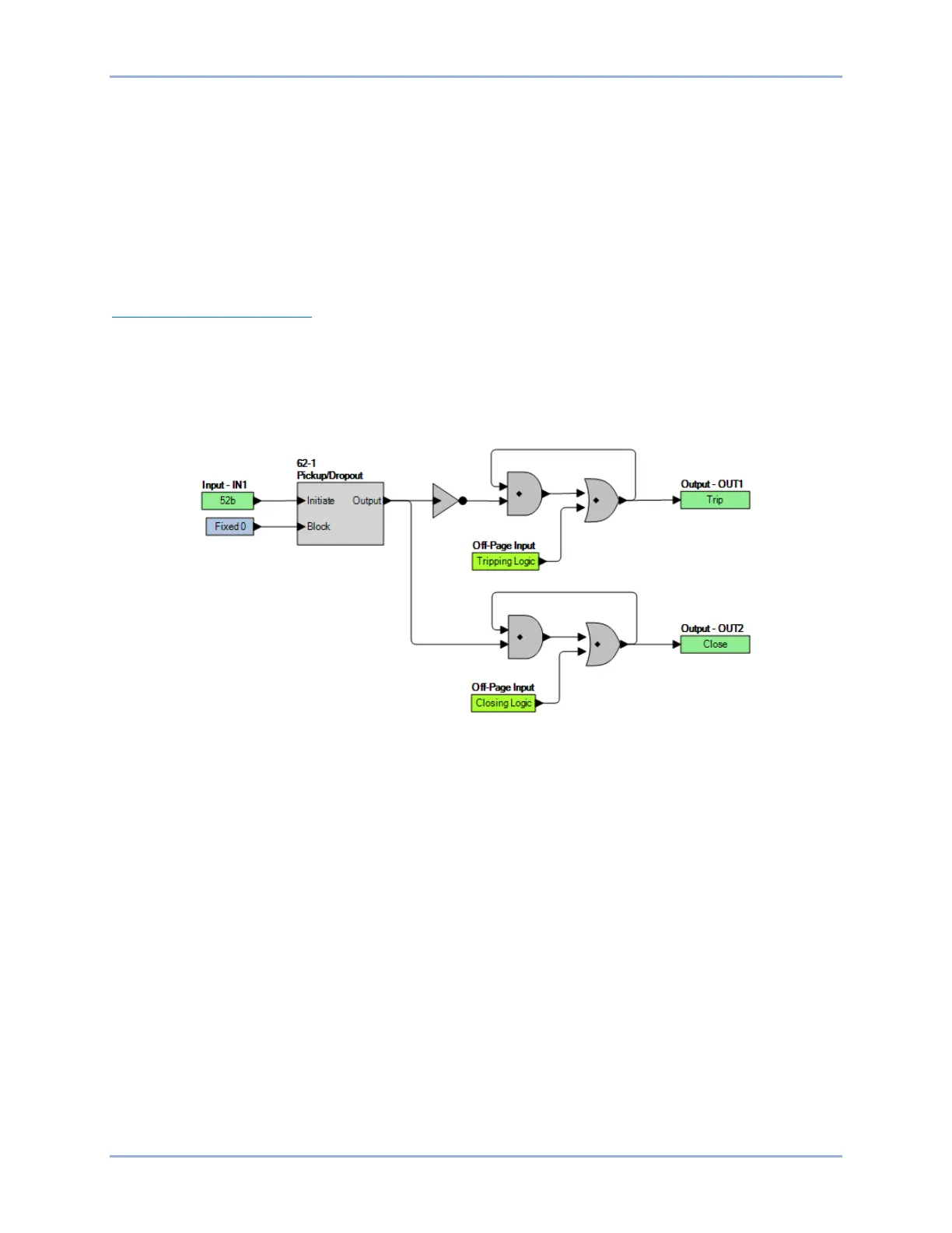
position logic, he/she can provide this logic by modifying the logic for the tripping output. To do this, use
one of the general purpose timers (62) and set it for Pickup/Dropout mode. Set the timer logic so that it is
initiated by the breaker position input and set the timer for two cycles pickup and two cycles dropout. The
same can be done for the closing output. Figure 4-6 provides a seal-in logic diagram.
Figure 4-6. Contact Output Seal-In Logic Diagram
Setting the Contact Outputs
BESTCOMSPlus Navigation Path: Settings Explorer, Programmable Outputs, Contact Outputs
HMI Navigation Path: Not available through the front panel
Settings and labels for the contact outputs are set using BESTCOMSPlus.
Each of the eight outputs has one setting and three labels. The setting consists of a Hold Attribute. The
labels include a label to describe the output, a label to describe the Energized State, and a label to
describe the De-Energized State. Labels are used by the BE1-11m's reporting functions.
To edit the settings or labels, use the Settings Explorer to open the Programmable Outputs, Contact
Outputs tree branch as shown in Figure 4-7.