83-4 9424200996
RTD Module BE1-11m
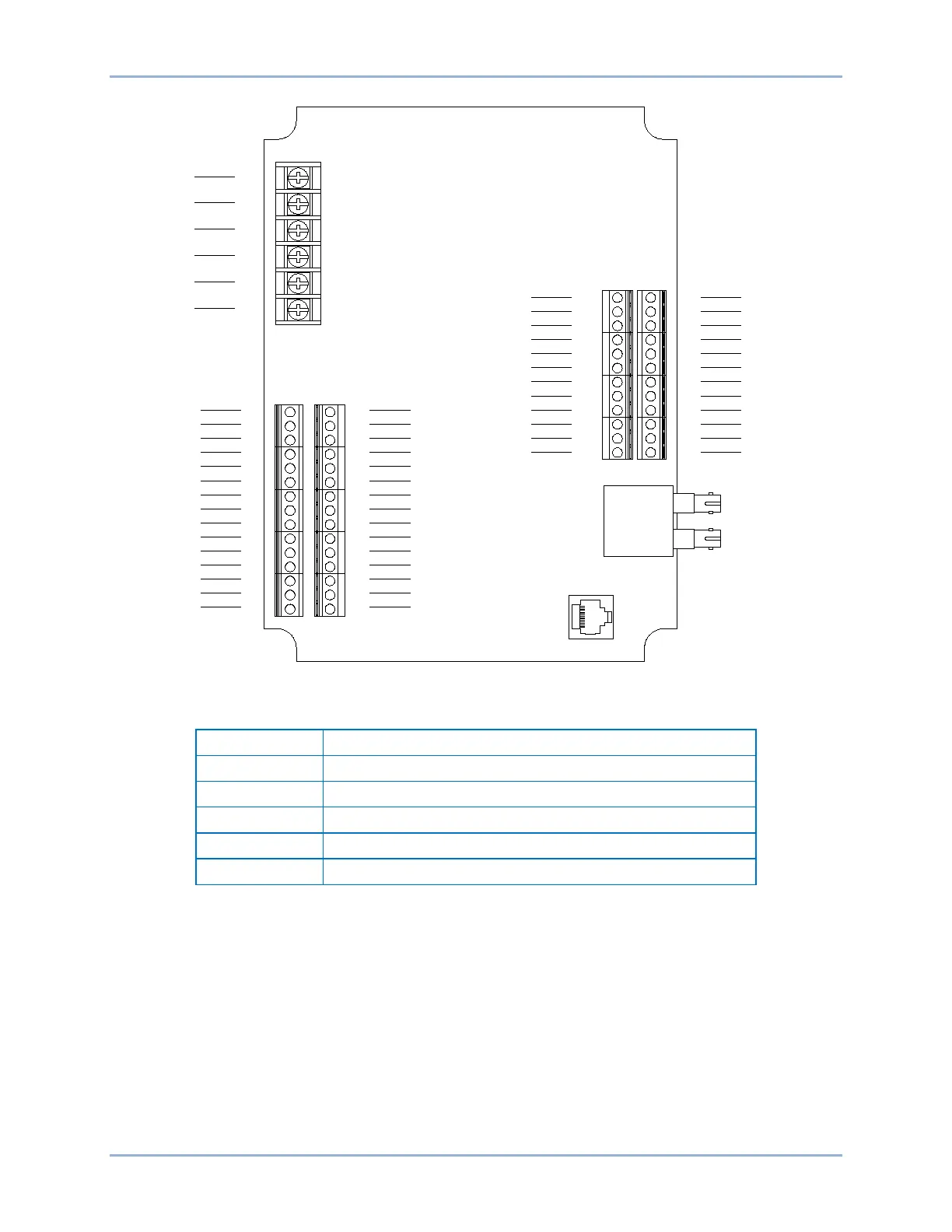
Figure 83-2. Input and Output Terminals
Table 83-3. Input and Output Terminals
Operating Power and Alarm Contacts
RTD Inputs 1, 3, 5, 7, 9, 11
RTD Inputs 2, 4, 6, 8, 10, 12
Analog Outputs 1 - 4 and RS485 Connection
External Analog Input Connections
Voltage input connections are shown in Figure 83-3 and current input connections are shown in Figure
83-4. When using the current input, AIN V+ and AIN I+ must be tied together.
7
8
9
10
11
12
13
14
15
16
17
18
19
20
21
22
23
24
25
26
27
28
29
30
31
32
33
34
35
36
48
47
46
45
44
43
42
41
40
39
38
37
60
59
58
57
56
55
54
53
52
51
50
49
RTD2+
RTD2-
COMM
RTD4-
RTD4+
RTD6+
RTD6-
COMM
RTD8-
RTD8+
RTD10+
RTD10-
COMM
RTD12-
RTD12+
RTD1+
RTD1-
COMM
RTD3-
RTD3+
RTD5+
RTD5-
COMM
RTD7-
RTD7+
RTD9+
RTD9-
COMM
RTD11-
RTD11+
RS485 C
RS485 B
RS485 A
NO CONN
AOUT4-
AOUT4+
AOUT3-
AOUT3+
AOUT2-
AOUT2+
AOUT1-
AOUT1+
AIN4I+
AIN4-
AIN4V+
AIN3I+
AIN3-
AIN3V+
AIN2I+
AIN2-
AIN2V+
AIN1I+
AIN1-
AIN1V+
P4 P3
J5 J4
1
2
3
4
5
6
PWR
PWR
GND
N.O.
COMM
N.C.
TB1
P0061-54