9-4 9424200996
Frequency (81) Protection BE1-11m
Logic Connections
Frequency element logic connections are made on the BESTlogicPlus screen in BESTCOMSPlus. The
frequency element logic block is illustrated in Figure 9-1. Logic inputs and outputs are summarized in
Table 9-1.
Figure 9-1. Frequency Element Logic Block
Table 9-1. Logic Inputs and Outputs
Disables the 81 function when true
True when the 81 element is in a trip condition
True when the 81 element is in a pickup condition
Operational Settings
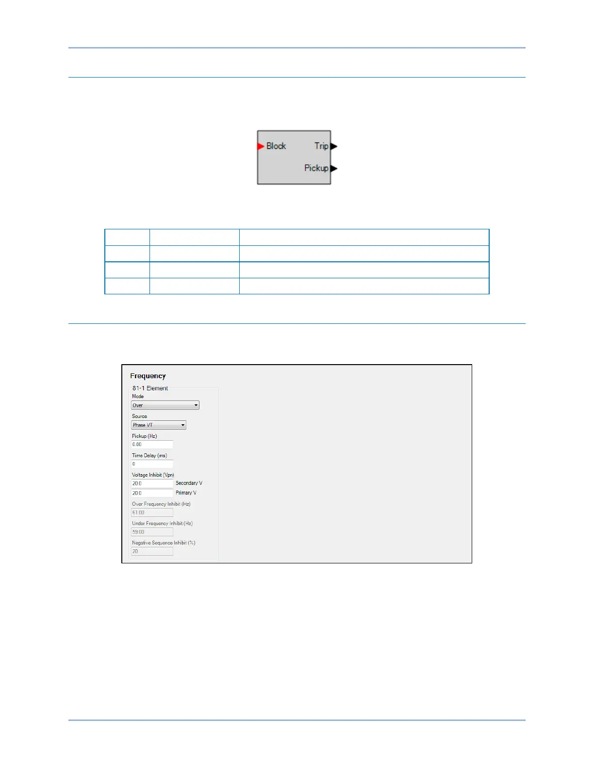
Frequency element operational settings are configured on the Frequency settings screen (Figure 9-2) in
BESTCOMSPlus.
Figure 9-2. Frequency Settings Screen
Phase-to-phase and phase-to-neutral settings depend on the Phase VT and Aux VT connection settings.
Refer to the Configuration chapter for more information on these settings.