30
5. Pin-Assignment / LED-Signaling
5.1 VCXG
5.1.1 Ethernet Interface (PoE)
Notice
The camera supports PoE (Power over Ethernet) IEEE 802.3af Clause 33, 48V Power
supply.
If the camera is simultaneously powered by the Power supply / Digital-IO port and the
Ethernet port (PoE), then the power supply via the Power supply / Digital-IO port is
prioritized.
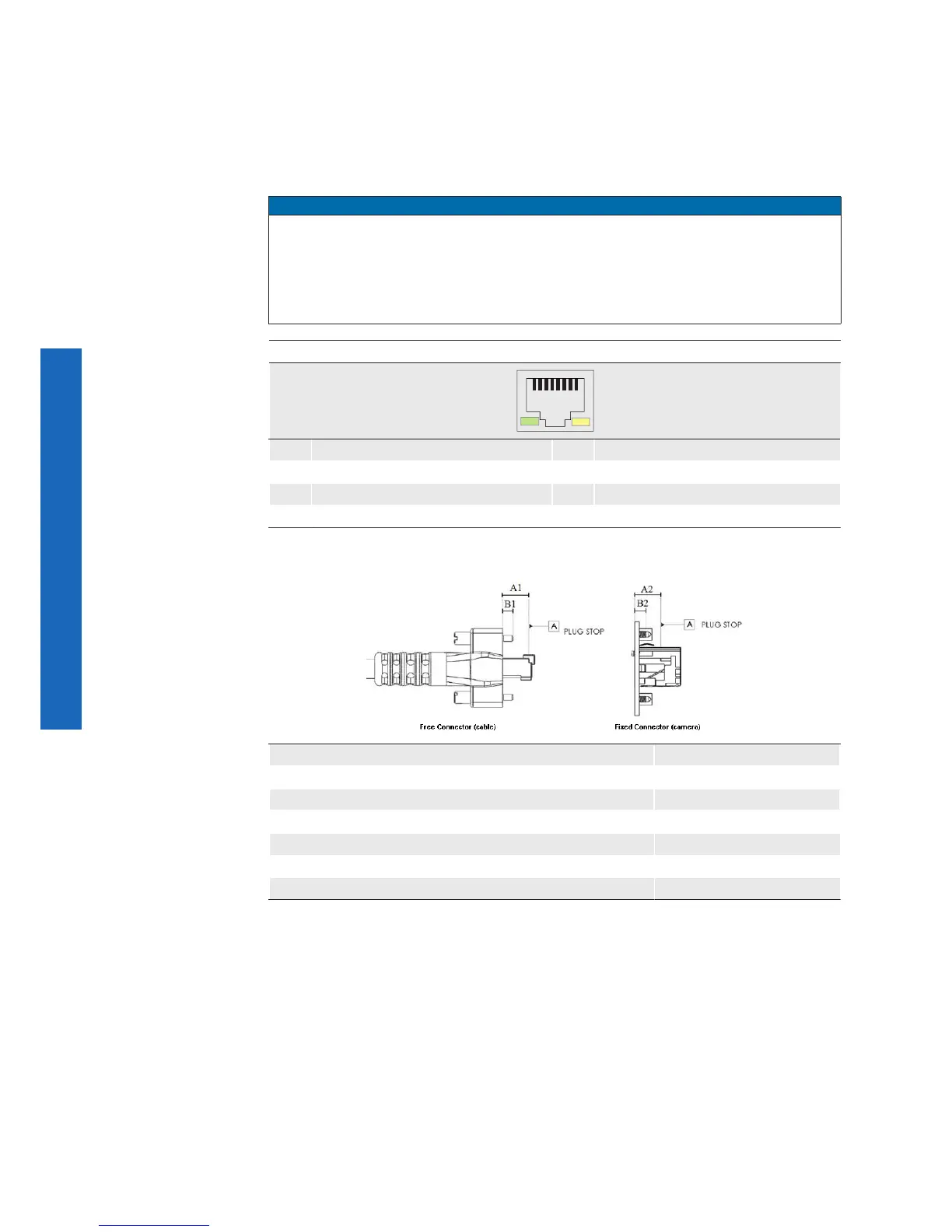
8P8C Modular Jack (RJ45) with LEDs
1
8
1 MX1+ 5 MX3-
2 MX1- 6 MX2-
3 MX2+ 7 MX4+
4 MX3+ 8 MX4-
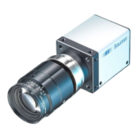
Dimension - Free Connector (cable) Type090
From overmold to plug stop (A1) 9.0mm (-0.50, +0.00)
From overmold to tip of thumbscrews (B1) 4.25mm (-1.00, +0.25)
Dimension – Fixed Connector (camera) Type090
From contact point to plug stop (A2) 9.0mm (-0.00, +1.00)
From contact point to bottom of thumbscrew thread (B2) 4.5mm (-0.00, +1)