6 DRAIN I Power MOSFET drain.
7 DRAIN I Power MOSFET drain.
8 DRAIN I Power MOSFET drain.
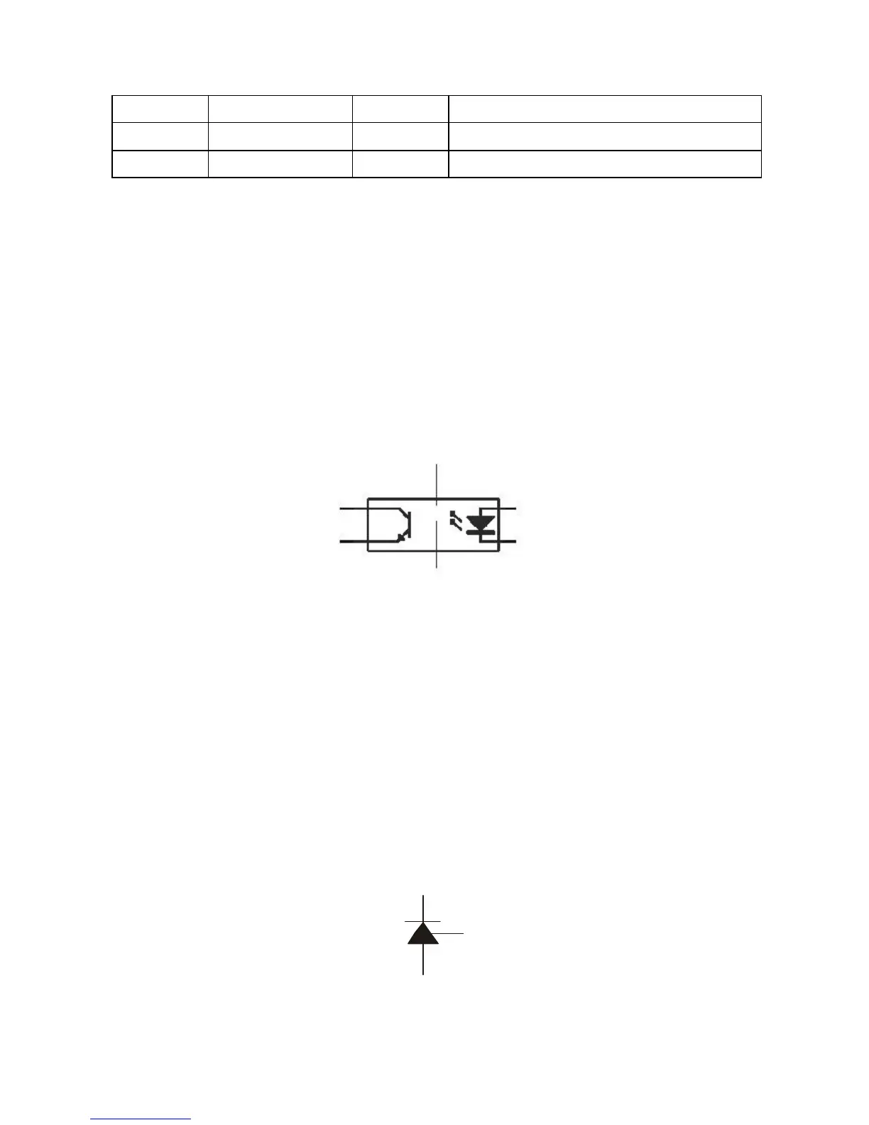
3.5.11 Function introduction to PH817
PH817 (U502) is a photoelectric coupler, shown as the figure 3.5.11.1. The right side is a light emitting
diode, which sends out light of different intensity according to the strength of voltage inputted from the right
side, generates photocurrent of different intensity on the left side according to light of different intensity, and
outputs from position D. The higher of the voltage inputted from the right side, the stronger of the light emitted
from light emitting diode and the larger of the photocurrent produced from position D. The lower of the voltage
inputted from the right side of photoelectric coupler, the weaker of the light emitted from light emitting diode
and the weaker of the current outputted from position D.
Figure 3.5.11.1 PH817 outside drawing
3.5.12 Function introduction to LM431A
LM431A (U503) is a 2.5V comparator, shown as the figure 3.5.12.1. Compared the inputted voltage of R end
with 2.5V, when voltage of R end is more than 2.5V, KA end is on and photoelectric coupler starts to send out
photocurrent; when voltage of R end is less than 2.5V, KA end is cutoff and photoelectric coupler does not send
out photocurrent. CPU+3.3V in power board circuit must be kept in 3.3V, for the function of comparator. No
matter more than or less than 3.3V, through on and off status of comparator, it will control the on state of the
output end of photoelectric coupler LM431A to adjust the output space occupation ratio of switch module to
control the output voltage of transformer and masthead the power.
K