2. Introduction to SCART terminal
(1) Working principle: SCART terminal integrates video and audio all together and it may transmit
video and audio signals at the same time. The operation is convenient, 21 pins in all and lies in the
central part on the rear side of the player.
(2) SCART terminal pin function is shown as the following table:
RGB_CVBS
AV_TV
Mode
switch
SCART
Component
video output
terminal
Optical,
terminal
XS701
MIC fetch
PDAT2
PDAT1
+10V
R#
L#
VIDEO#
Y1
Pb
Pr
SPDIF
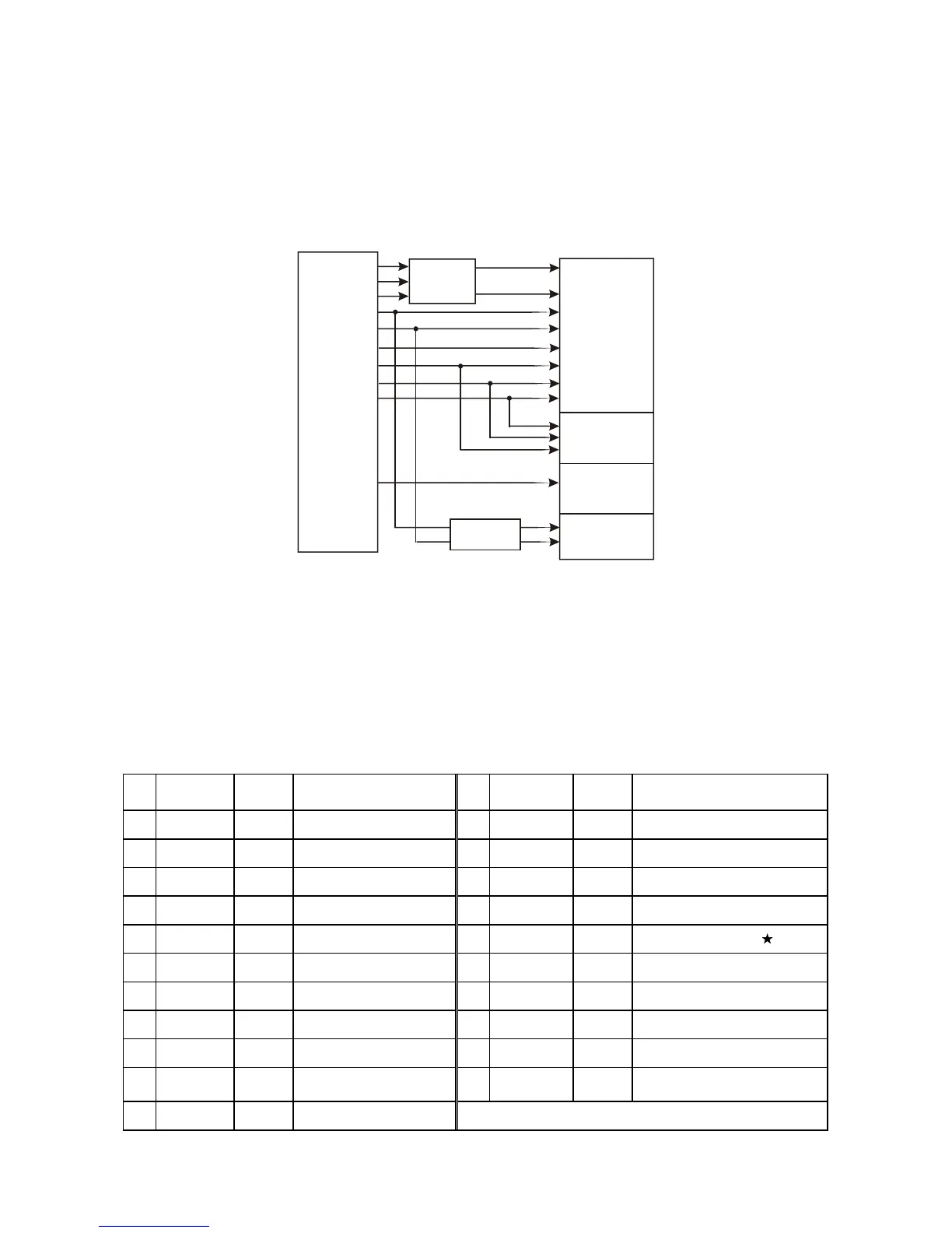
3.1.14 AV output board circuit
1. AV output board is mainly composed of audio/video output terminal,
AV
3.1.14.1:
SCART output terminal,
mode switch circuit and filtering circuit. output board outputs different signals to connect with the
corresponding external equipment. AV output board circuit block diagram is shown as in the following
figure
Figure 3.1.14.1 AV output board circuit block diagram
XS702
Pin Name
Signal
direction
Function descr iption Pin Name
Signal
direction
Function descr iption
1 A(B)OUT I Audio right channel input 12 NC Netw ork communication data line 2
2 A(B)IN O Audio right channel output 13 RETURN Pr signal ground
3 A(A)OUT I Audio left c hannel input 14 RETURN Blanking signal ground
4 A-COM Audio signal ground 15 RED I/O I/O Pr signalI/O port
5 RETURN Pb signal ground 16 BLK I/O I/O Blanking signal I/O port
6 A(A)IN O Audio left c hannel output 17 RETURN Blanking signal ground
7 BLUE I/O I/O Pb signalI/O port 18 TRTURN Composite video signal ground
8 FUNCSW I Function selection jack 19 V-OUT I Composite video signal input
9 RETURN Y1 s ignal ground 20 V-IN O Composite video signal output
10 CONT I/O
Netw ork communication data
line 2
21 GND Commo n
11 GREEN I/ O I/O Y1 s ignal I/O port