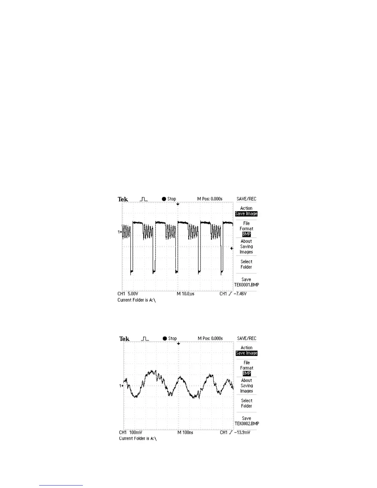
2. RFO signal waveform diagram of pin 17 of XS301
This section collects signal waveform diagram of audio, video and each unit circuit with the purpose
to help servicing personnel to judge where trouble lies in accurately and quickly to improve servicing
skills. For the difference of oscillograph's type, model and tuner, a certain difference may exist, so the
servicing personnel are expected to pay more attention to check in daily operation.
1. Waveform diagram for pulse DC of power board D513 anode
Section Four Waveform diagram
- 45 -