equalization Frequency compensation inside MT1389, another part of signals are changed into digital
signals through internal A/D converter. When loader is reading CD/VCD signals, these signals are
conducted EFM demodulation inside MT1389, and then outputted to latter stage for AV decoding after
finishing CIRC (Cross-Interleaved Reed-Solomon Code) error correction inside. When loader is reading
DVD signals, these signals are conducted ESM demodulation inside MT1389, and then sent to latter
stage for decoding after finishing RSPC error correction inside. Normal DVD player has a open/close
circuit to control the in and out of door to reach the purpose of coneying discs; PDVD adopts manual
open means and whether it is close to proper position can be checked by detect switch.
3. Explanation to servo terms
(1) FOO: when rotating, disc may probably move upwards or downwards slightly to make the focus
of laser emitted by laser head cannot justly fall on data pit of disc, so laser head is required to move
upwards or downwards to make focus aim at data pit justly. When laser head is moving upwards or
downwards, it means that pick-up is making focus acts.
(2) TRO: data information is saved in disc in form of tracks. When disc is rotating, trace deviation
will produce and now laser head is required to be adjusted. In this process, it is objective, but the entire
pick-up, that moves forwards or backwards, and the moving range is very small.
(3) FMO: similar to acts of trace, the acts of feed are larger than those of trace. Feed conducts a
large scale movement firstly, and then trace moves slightly in this range. Feed moves for a while, and
does not move for another while; but trace moves all the time. Feed is rough adjustment and trace is fine
and acts are obvious when pwer on and selecting tracks.
(4) DMO: it is the top that holds up disc. Its rotation speed decides that of disc. Its rotation is
generated by an individual DC electric machine, in which rotation speed of DVD is twice over that of CD.
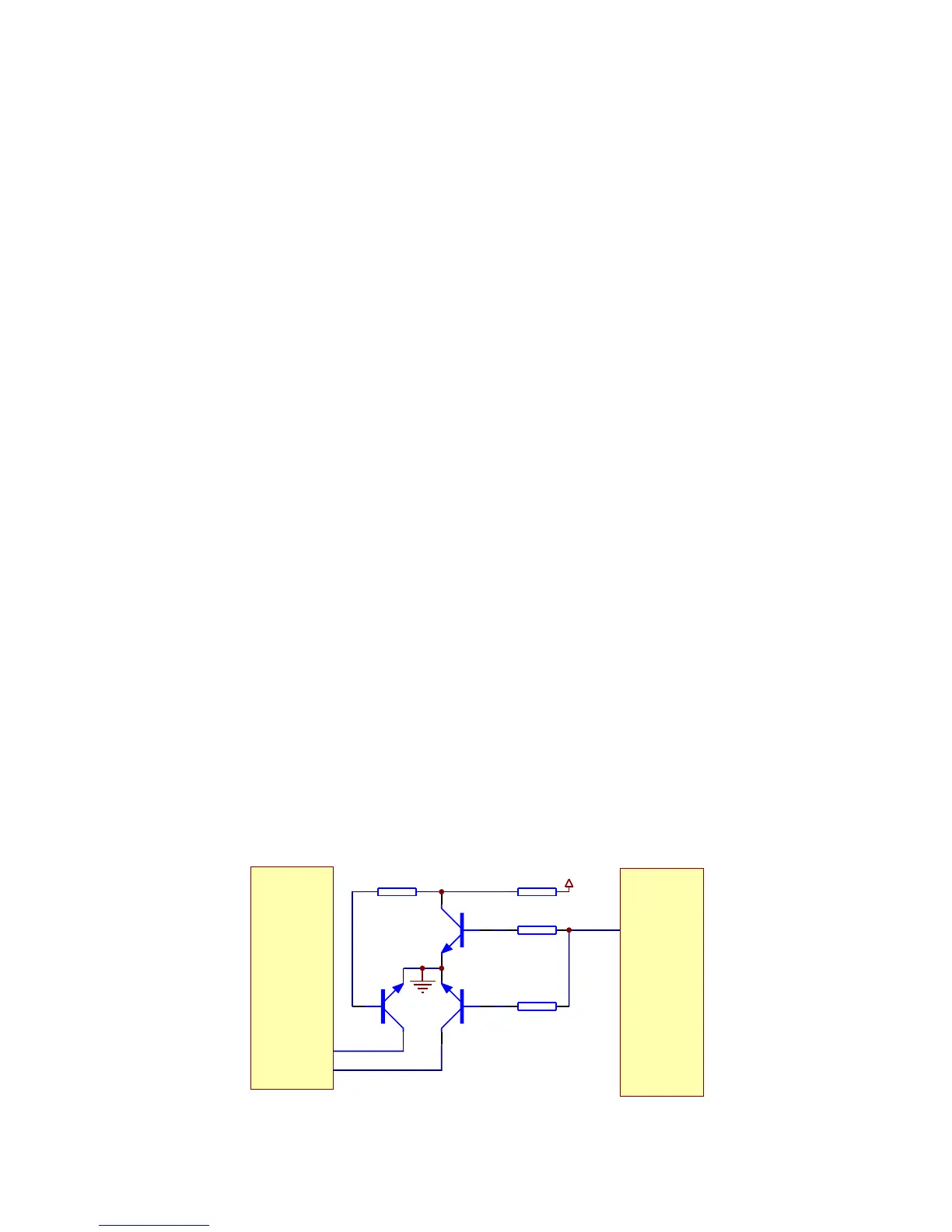
3.2.3 CD/DVD conversion circuit
1. CD/DVD conversion circuit is shown as in the following figure 3.2.3.1:
R309
10K
R308
100K
R311
10K
R310
100K
Q303
2SK3018-S
Q304
2SK3018-S
Q305
3904-S
IOA
AVCC
MT1389E
XS301
17
18
Figure 3.2.3.1 CD/DVD conversion circuit diagram
- 19 -