User information storage: information content set by user is saved inside EEPROM, if user does not
refresh or reset this information, it will saved in IC permanently.
Audio, video output circuit: at present, MT1389 all integrates video D/A converter, MT1389E inside
integrates audio D/A converter, manufactures select according to their own needs. Please refer to
circuit principle diagram and audio circuit explanation for details.
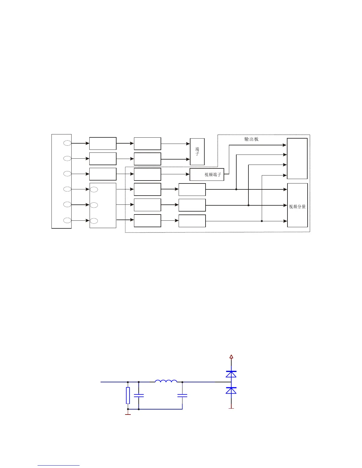
3.2.8 Video circuit
1. Video signal flow chart diagram is shown as in the following figure 3.2.8.1:
MT1389
187
185
183
182
YUV3
L227
YUV4
L701
YUV5
L702
YUV6
L703
XS204
7
9
5
VIDEO-SY
VIDEO-SC
VIDEO-CVBS
VIDEO-G/Y
VIDEO-B/U
VIDEO-R/V
Pr
Pb
Y1
VIDEO
S
JK703
SCART
JK703
AV
191
189
YUV1
L225
YUV2
L226
D211
D703
D704
D705
D209
D210
Figure 3.2.8.1 Video signal flow chart
2. Working principle: MT1389E has built-in video D/A conversion circuit, video output has R/B/G
Y/Pb/Pr Y/Cb/Cr CVBS Y/C output mode, in which R/B/G Y/Pb/Pr Y/Cb/Cr Y/C cannot output at the
same time and need the switch through software. CVBS is a separate output mode, 4-path video signal
outputted by MT1389, through video filtering clamping, output to AV board.
Shown as in the figure 3.2.8.2, capacitor C287, C288 and inductor L214 compose a low-pass filter
to filter high frequency disturbance signal except useful signal; dual diode D211 composes a limiter
circuit, known from features of diode that the max amplitude of composite video signal CVBS cannot be
over 5.7, and the mix cannot be less than -0.7, thus the high voltage signal from TV set can be avoided
burning down the player.
R248
75R
C288
101
C287
101
VGND
L227
1.8uH
YUV3
5VV
VGND
VIDEO_CVBS
D211
1N4148*2
Figure 3.2.8.2 Video output circuit
- 25 -