Base electrode B Collector C Em itto r E Base electrode B Collector C Em ittor E
Read disc 5.06 5 5.06 5.01 5.03 5.06
Open disc tray to
proper position
4.79 4.77 5.06 4.77 4.79 5.06
Open disc tray 4.74 5.05 4.74 4.76 0.2 4.76 5.06 4.76 4.33 4.76 4.76 5.02 4.76 5.06
Close disc tray 4.74 4.33 4.74 4.76 5.05 4.76 5.06 4.76 5.03 4.76 4.79 0.2 4.79 5.06
Base electrode B Collector C Em itto r E Base electrode B Collector C Em ittor E
Read disc 0 5 0 0 5.03 0
Open disc tray to
proper position
0 4.77 0 0 4.79 0
Open disc tray 0 0.93 0 4.76 0.2 4.76 0 0 4.79 5.02 4.79 0
Close disc tray 0 4.76 5.05 4.76 0 0 0.93 0 4.79 0.2 4.79 0
Base electrode B Collector C Em itto r E
Read disc 0 0 0 0 0
Open disc tray to
proper position
0 0 0 0 0
Open disc tray 0 0.63 0 0 0 0 3.12 0 0
Close disc tray 0 0 0.93 0 0 0 0 3.12 0
State
State
State
Q309
Q307Q306
Q308
Q310
OUT IN
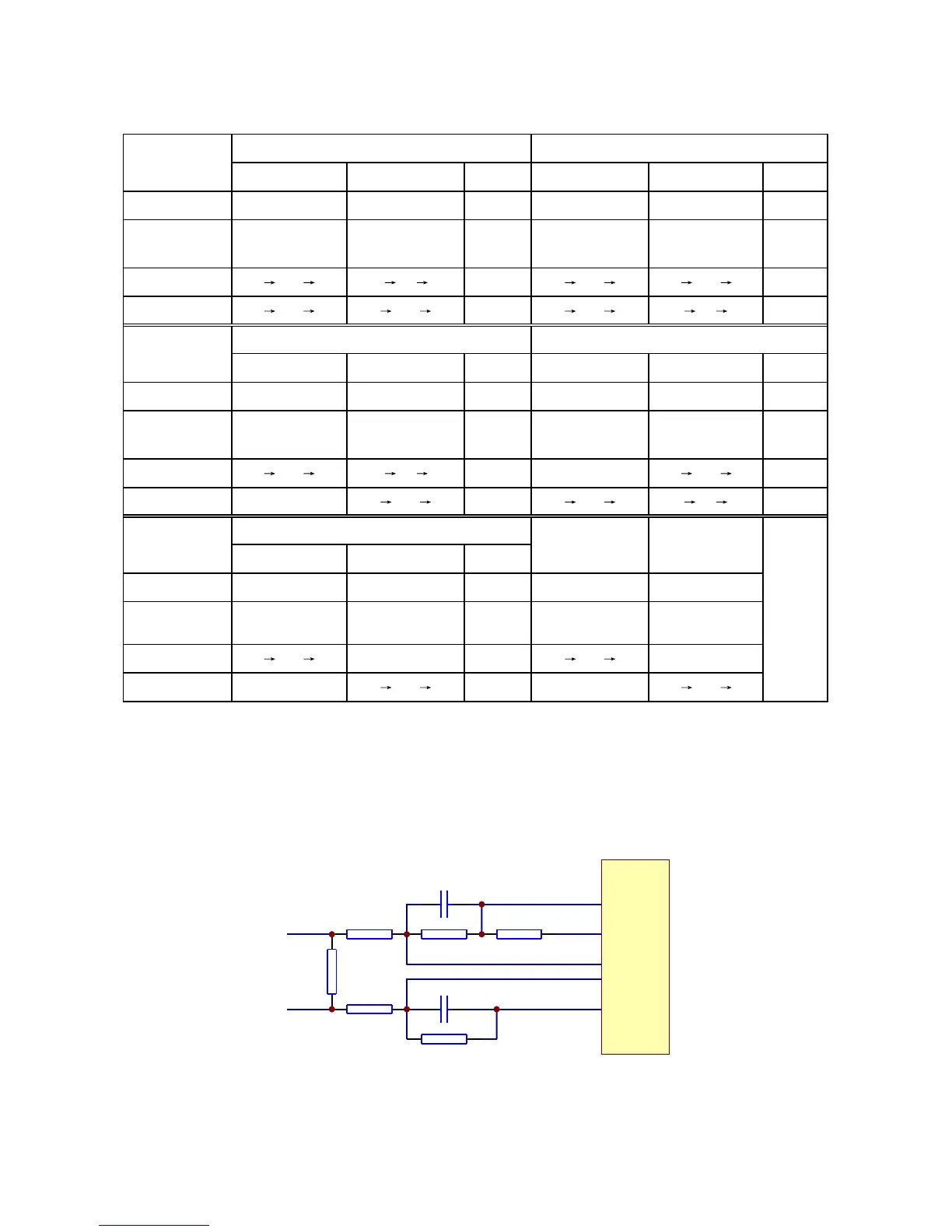
3.2.6 Main axis control circuit
1. Main axis control circuit is shown as in the following figure 3.2.6.1:
R321
1R
R320
150K
R319
150K
R322 680K
R317 680K
R318
0R
C307 222
ADIN
OP-
OP+
V1P4
SP-
OPO
C308 222
SPL-
MT1389
Figure 3.2.6.1 Main axis control circuit diagram
- 22 -