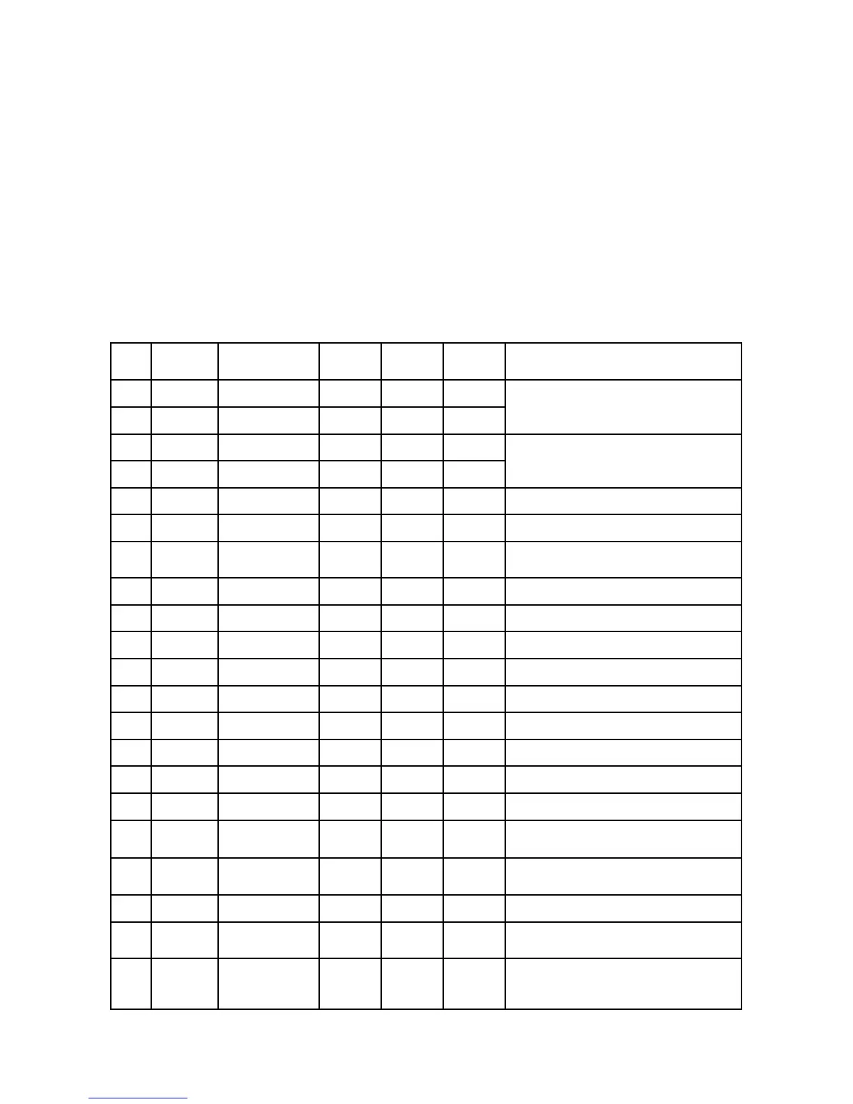
Pin Name
Signal flow
direction
DVD disc CD disc No disc Function description
1 F- Input loader 2.52 2.34 0.46
2 F+ Input loader 2.49 2.49 0.93
3 T+ Input loader 2.53 2.51 0.94
4 T- Input loader 2.58 2.51 0.93
5 C Input MT1389 2.2 2.25 2.04 Disc data signal
6 D Input MT1389 2.2 3.2 2.04 Disc data signal
7 IOA Input MT1389 0.01 3.2 3.21
Disc identification signal, CD is 3.3V, DVD
is 0V
8 RF Input MT1389 2.21 2.53 1.28 The sum of disc data signal
9 A Input MT1389 2.17 2.22 2.04 Disc data signal
10 B Input MT1389 2.19 2.27 2.04 Disc data signal
11 F Input MT1389 2.07 2.44 2.03 Supplementary signal used in trace
12 GND Ground 0.01 0.01 0 Grounding
13 V20 Input loader 2.04 2.06 2.03 Reference voltage
14 Vcc Input loader 5.04 5.04 5.02 Supply voltage for loader
15 E Input MT1389 2.06 2.45 2.03 Disc data signal
16 Blanking haning in air 0.01 0 0 unused
17 VR-CD Input loader 0.21 0.01 0
Through the handling inside loader, make
sure MD11 is 180mV when reading CD
18 VR-DVD Input loader 0.01 0.2 0
Through the handling inside loader, make
sure MD11 is 180mV when reading DVD
19 LD-CD Input loader 0.09 2.1 0 CD laser power control signal
20 MDII Input MT1389 0.21 0.2 0 CD and DVD laser power monitoring signal
21 HFM Input loader 5.04 5.04 5.02
High frequency overlapping signal produces
laser with different wave length inside
loader
Focus error signal is added to two sides of
pick-up focus coil
Trace error signal is added to two sides of
pick-up trace coil