27 GR4 O Grid output
28 GR3 O Grid output
29 GND I Ground
30 GR2 O Grid output
31 GR1 O Grid output
32 GND I Ground
3.5.10 function introduction to VIPer22ADIP
1. DESCRIPTION
The VIPer22A (U501) combines a dedicated current mode PWM controller with a high voltage Power
MOSFET on the same silicon chip. Typical applications cover off line power supplies for battery charger
adapters, standby power supplies for TV or monitors, auxiliary supplies for motor control, etc. The internal
control circuit offers the following benefits:
Large input voltage range on the VDD pin accommodates changes in auxiliary supply voltage. This
feature is well adapted to battery charger adapter configurations.
Automatic burst mode in low load condition.
Over voltage protection in hiccup mode.
2. FEATURES
◆ FIXED 60 KHZ SWITCHING FREQUENCY
◆ 9V TO 38V WIDE RANGE VDD VOLTAGE
◆ CURRENT MODE CONTROL
◆ AUXILIARY UNDERVOLTAGE LOCKOUT WITH HYSTERESIS
◆ HIGH VOLTAGE START UP CURRENT SOURCE
◆ OVERTEMPERATURE, OVERCURRENT AND OVERVOLTAGE PROTECTION WITH
AUTORESTART
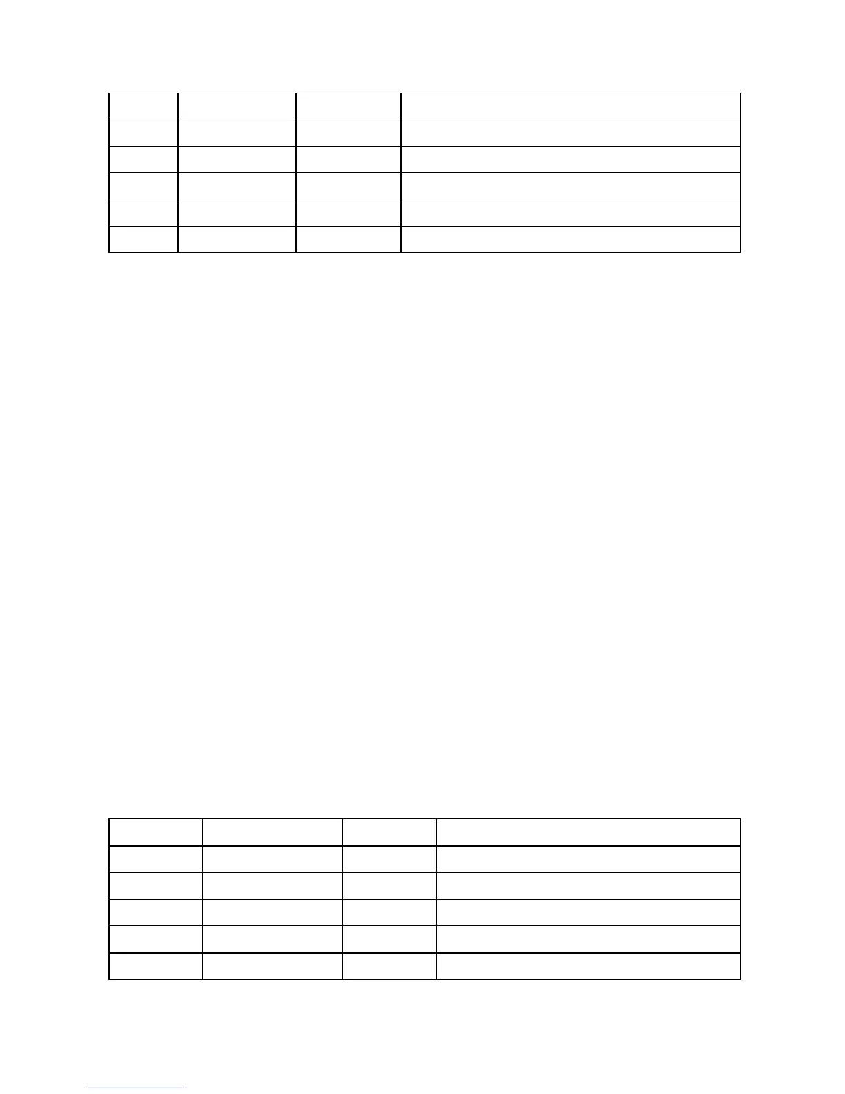
3. PIN DESCRIPTION
PIN Symbol I/O Description
1 SOURCE O Power MOSFET source and circuit ground reference.
2 SOURCE O Power MOSFET source and circuit ground reference.
3 FB I Feedback input.
4 VDD I Power supply of the control circuits.
5 DRAIN I Power MOSFET drain.
- 77 -