2. Working principle: MT1389 has built-in DAC conversion circuit, which stimulates audio signals to
output from decode chip directly, through audio amplifying and filtering circuit, directly output audio
signals to audio terminal. Another path of L/R signal outputs to headphone circuit of MIC board for
processing and then output from headphone.
3. External Karaoke input and output
Trough CS5340 A/D conversion circuit, MIC signals switches to digital audio signals to input to
decode chip for echo and volume processing and then output together with audio signals L/R to fulfill the
purpose of Karaoke.
3.2.11 Mute circuit
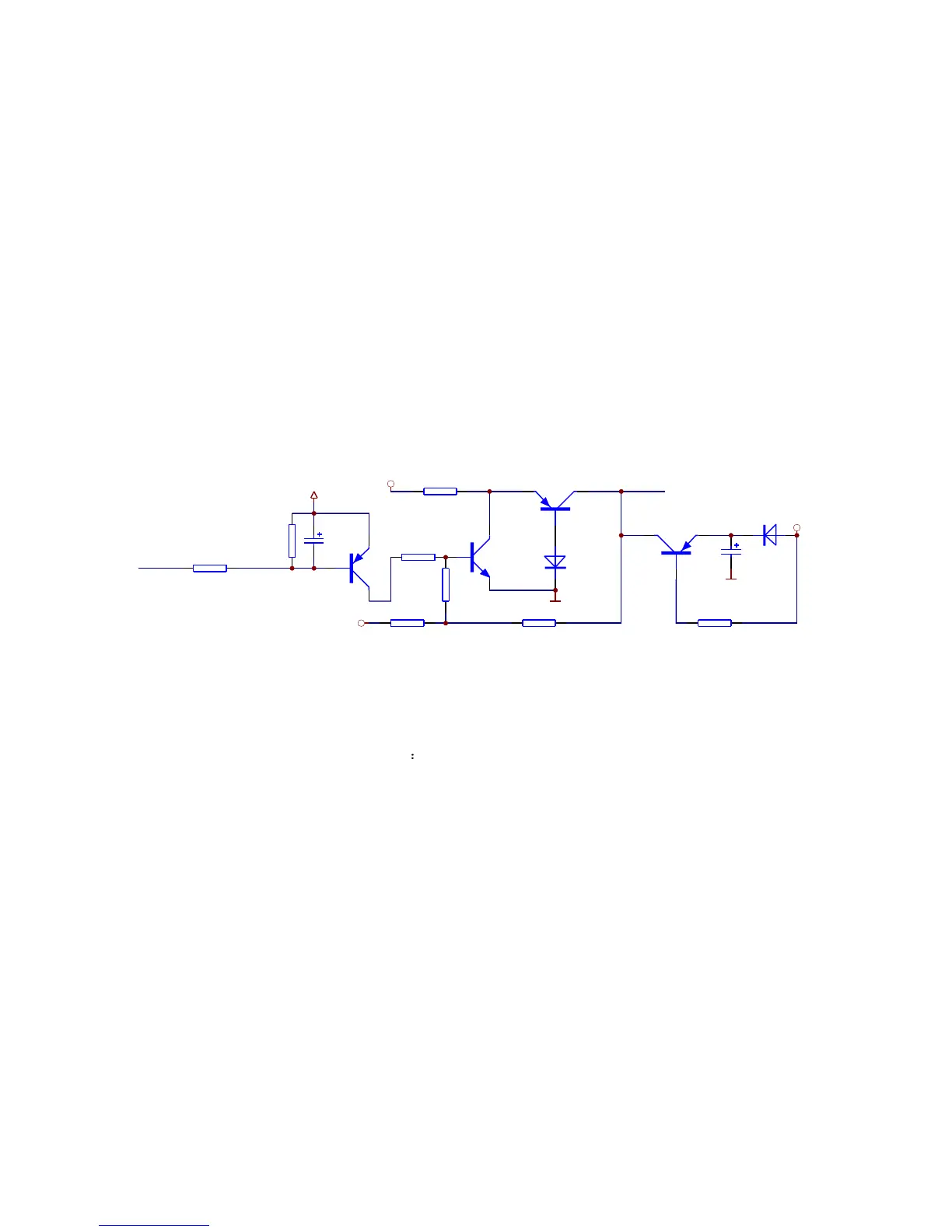
1. Mute circuit is shown in the figure 3.2.11.1:
VMUTE
R2108
10K
+9V
R2109
10K
R2104
1K
D203
1N4148
DV33
R2103
1K
AGND
D204
1N4148
-9V
MUTE-1
TC235
100uF/10V
AGND
R2106
10K
Q212
2SC1815-YS
Q213
1015
Q214
1015
Q211
1015
R2101
100K
TC238
100uF/10V
DV33
R2105
10K
R2107
10K
Figure 3.2.11.1 Mute circuit
2. Working principle of quieting circuit
TE to make Q211 on, voltage of Q211B electrode is about
2.7V, voltage of Q211 collector electrode is about 3.3V, so Q212 is also on, voltage of B electrode is
about 0.7V, voltage of Q213 E electrode is close to zero, Q213 cuts off, MUTE-1 is negative voltage
which is added to base electrode of mute tube of audio output end to make mute tube cutoff, audio
signals output through being amplified by 4580. When in mute, MT1389E has no audio signals to output
to operational amplifier, so audio output end of the player has no audio output, because electrical
elements and IC in circuit will produce some noise to send to audio output end of the player, in order to
filter these noise, decode chip outputs a high level to VMUTE to make Q211 cutoff, so Q212 cuts off, +5V
power transmits to base electrode of switch pipe Q205 - Q210 through E, C electrode of Q213 and circuit
is in mute.
When machine is not playing discs, decode chip outputs a high level signal to VMUTE to make
circuit enter circuit mode.
When the player is playing normally, shown in the figure 2.11.1, chip outputs analog audio signals
and a low level signal at the same time to VMU
- 27 -