(3) SCART terminal function selection is shown as the following table:
Note: PDAT0 and PDAT2 are used to control input voltage of pin 8 of SCART terminal; PDAT1 is
used to control voltage change of pin 16 of SCART terminal and the voltage on pin 16 controls SCART
terminal to select RGB mode or CVBS mode.
3.2.15 Panel control circuit
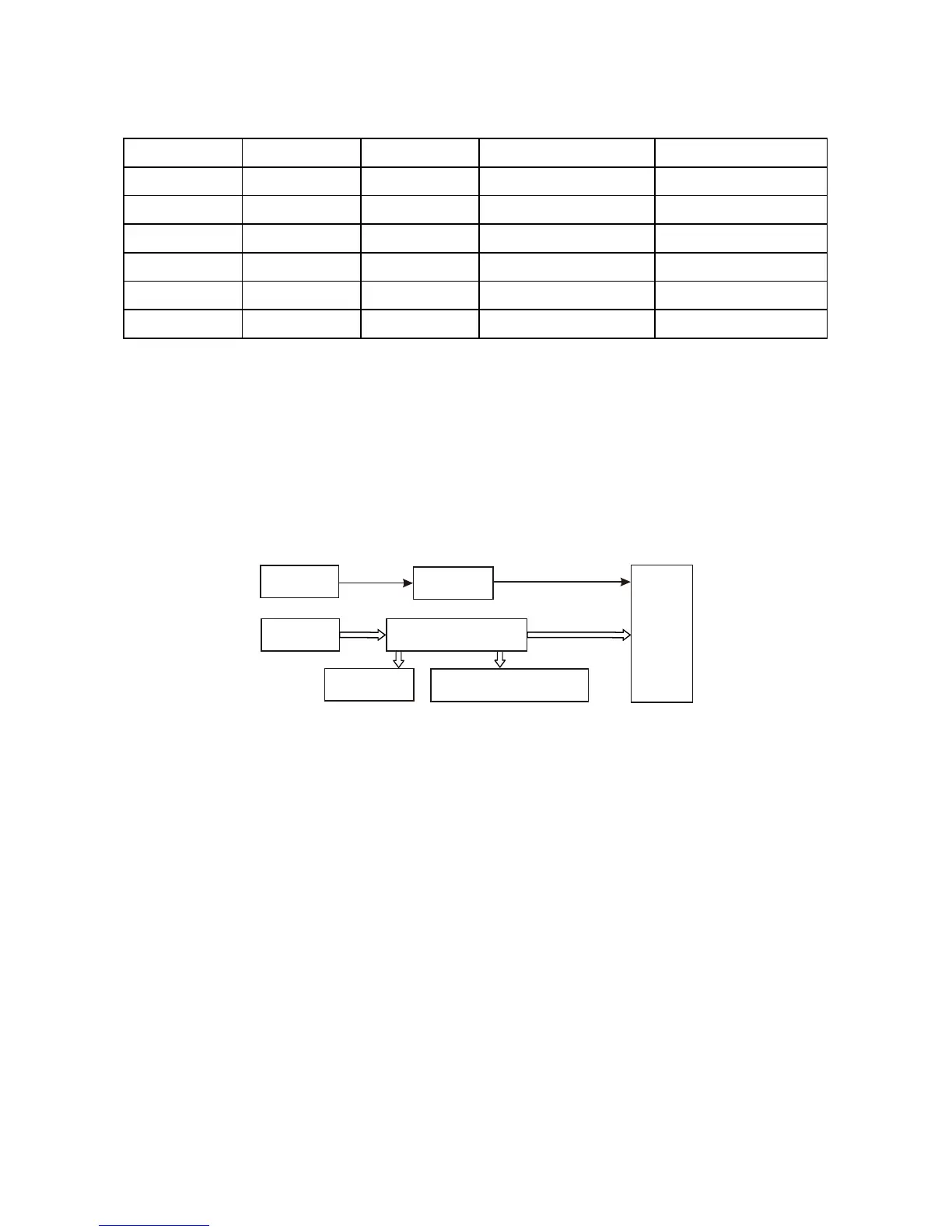
1. Panel control circuit block diagram is shown in the figure 3.2.15.1:
Figure 3.2.15.1 Panel control circuit block diagram
2. Working principle
Panel control components are divided into main panel and subsidiary board parts. Main panel is
mainly composed of LED screen, drive chip PT6961, remote control IR sensor, buttons and indicator
light; and subsidiary board is mainly composed of power button and power indicator light.
Function of U401 (PT6961) is to process data signals sent from decode board and then drive
display screen to display the relevant state, and scan panel buttons matrix at the same time, then
process button information and send to CPU in the means of digital signals to control the player to make
the relevant action.
Pin 2 of remote control IR sensor HS0038B3V is 5V power supply pin, pin is grounded, pin 3 is
output pin. After receiver processes button information of remote control, it outputs from pin 3 to send to
decode board directly.
Remote
controller
IR sensor
Decode
Button
LED screen
LEDST, LEDCK, LEDAT
Light emission diode
U401(PT6961)
- 31 -