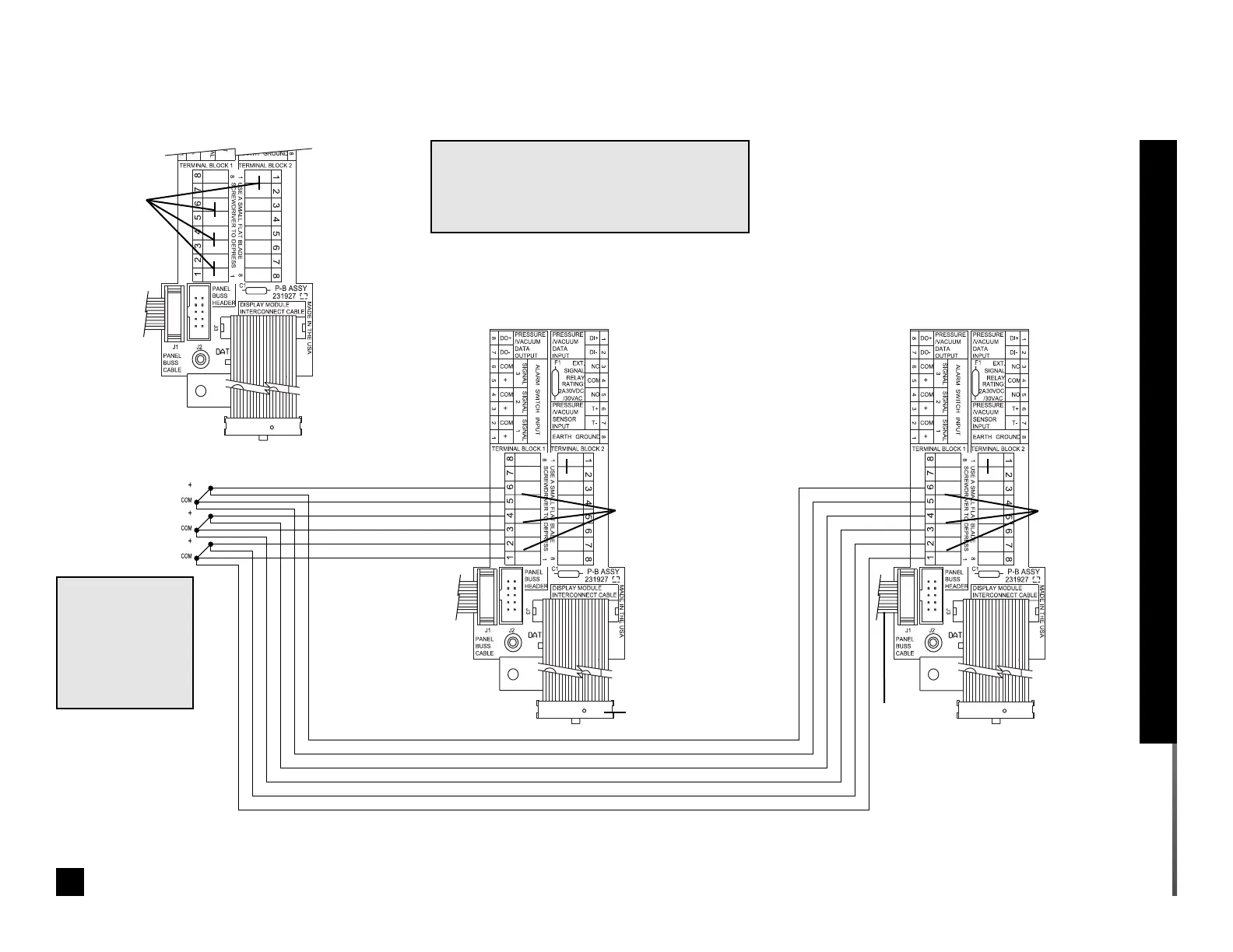
Factory installed
jumper wires
NOTE 1:
Remove only jumper wires from the terminals
that are to have field wiring connected.
Leave all other jumper wires in place.
Schematic 3. Digital Display Module User-Assigned Signals
Ten- w i r e r i b bon
cable to adjacent
module
Digital display module
interconnect board
Supply Status
Signal Switches
SIGNAL 3
SIGNAL 2
SIGNAL 1
NOTE 2:
Dry contact
switches activate
alarms upon
opening (normally
closed)
Digital display module
interconnect board
Wiring terminals accept up
to #14 AWG wire
Twenty-wire
ribbon cable to
digital display
module chassis
Twenty-wire ribbon cable to
digital display module chassis
Ten- w i r e
ribbon cable
to adjacent
module
17
Part No. 6-847681-00 Rev. D02
Wiring Schematic: Digital Display Module User-Assigned Signals
Jumpers wires
removed.
See Note 1.
Jumpers wires
removed.
See Note 1.