Commissioning
EL3773 85Version: 2.5
6.4 Basic function principles
Note
RMS value (rms) specifications
All AC value specifications in this documentation such as RMS specifications (
rms
) refer to a
50/60 Hz 3-phase mains network with a sinusoidal waveform.
The EL3773 has 6 analog input channels which are measured simultaneously in their respective measuring
ranges. The properties are discussed below in the order of the data processing.
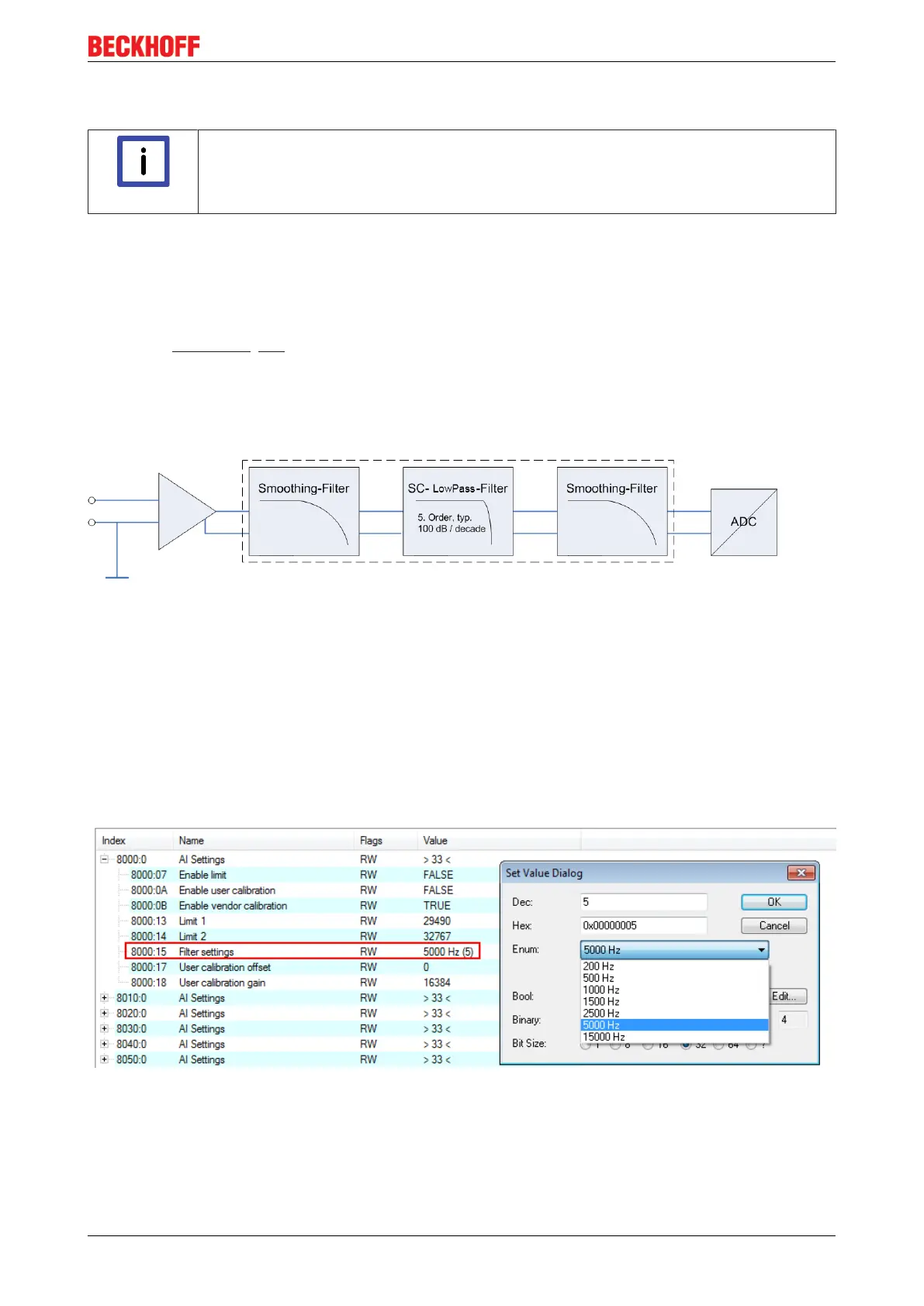
Input filter
Each channel has a 5
th
order low-pass filter with Bessel characteristic which can be parameterized via the
CoE setting 0x8000:15 [}95]. The corresponding anti-aliasing filters are placed up or downstream and are
adapted automatically.
The filter setting of channel 1 also applies to channels 2 to 6; the corresponding CoE object cannot be
written in these channels. All 6 input channels are thus subject to the same filter characteristic.
The input filter cannot be deactivated.
Fig.98: Data flow diagram input filter
The following steps can be selected:
• 200 Hz
• 500Hz
• 1kHz
• 1.5 kHz
• 2.5 kHz
• 5 kHz
• 15kHz
Fig.99: Filter setting via the CoE object "Filter settings" (Index 0x8000:15)
The amplitude curve can be represented accordingly: