Mounting and wiring
EL70x152 Version: 4.4
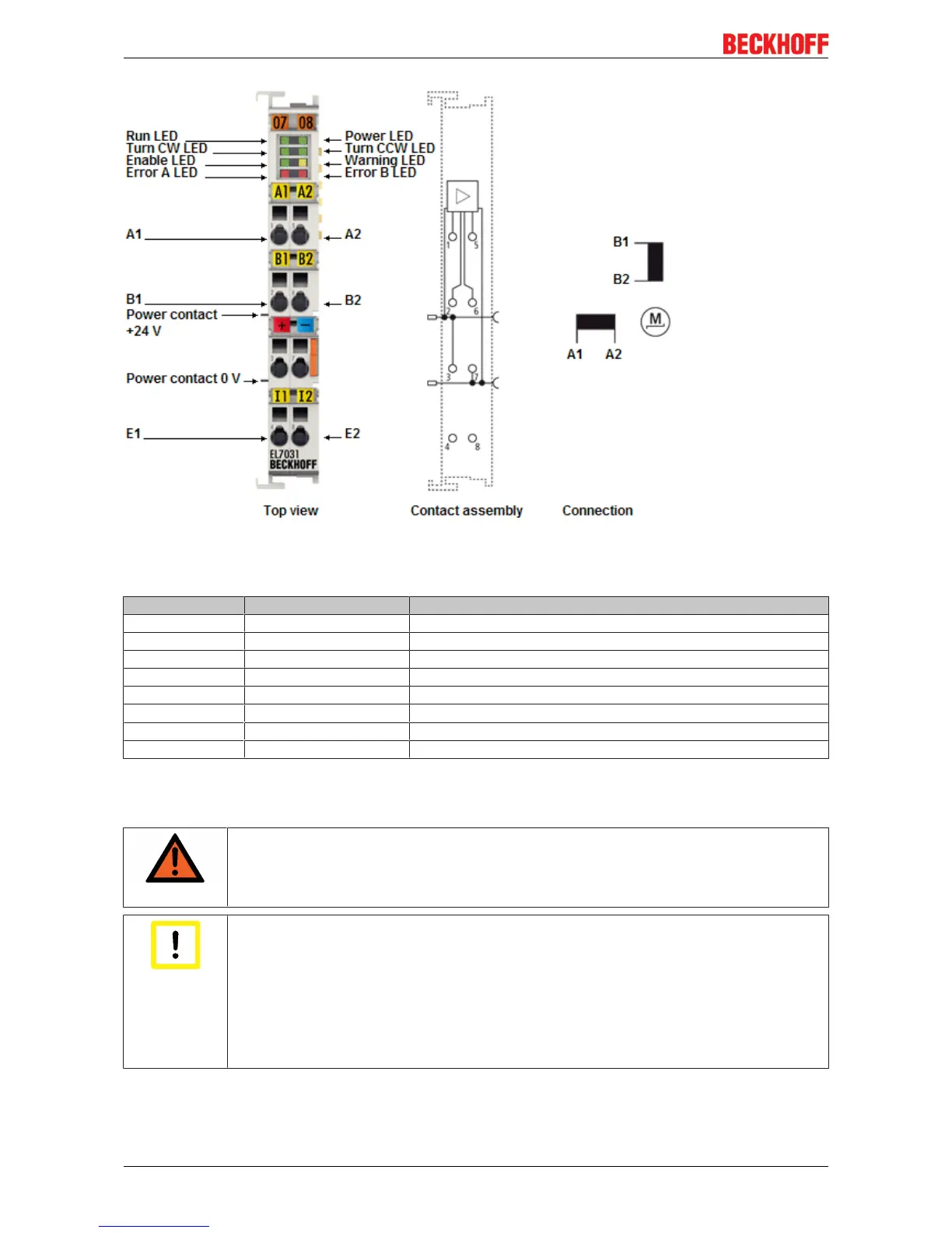
Fig.34: Connection EL7031
Connection
Terminal point Name Signal
1 A1 Motor winding A
2 B1 Motor winding B
3 Motor supply +24 V Supply for output stages (from positive power contact)
4 Input 1 Digital input 1 (24V
DC
)
5 A2 Motor winding A
6 B2 Motor winding B
7 Motor supply 0 V Supply for output stages (from negative power contact)
8 Input 2 Digital input 2 (24V
DC
)
4.7.2 General connection examples
WARNING
Risk of injury through electric shock and damage to the device!
Bring the Bus Terminals system into a safe, de-energized state before starting mounting,
disassembly or wiring of the Bus Terminals.
Attention
Connect the motor strands correctly!
Connect the windings of a motor strand only to the terminal points of the same output driver
of the stepper motor terminal, e.g.:
- one motor strand to terminal points A1 and A2,
- the other motor strand to terminal points B1 and B2.
Connecting a motor strand to the terminal points of different output drivers (e.g. to A1 and
B1) can lead to destruction of the output drivers of stepper motor terminal!
Connection types
The EL7031 Stepper Motor terminal has bipolar output stages and can control bipolar and unipolar motors.