987892AF
3-15
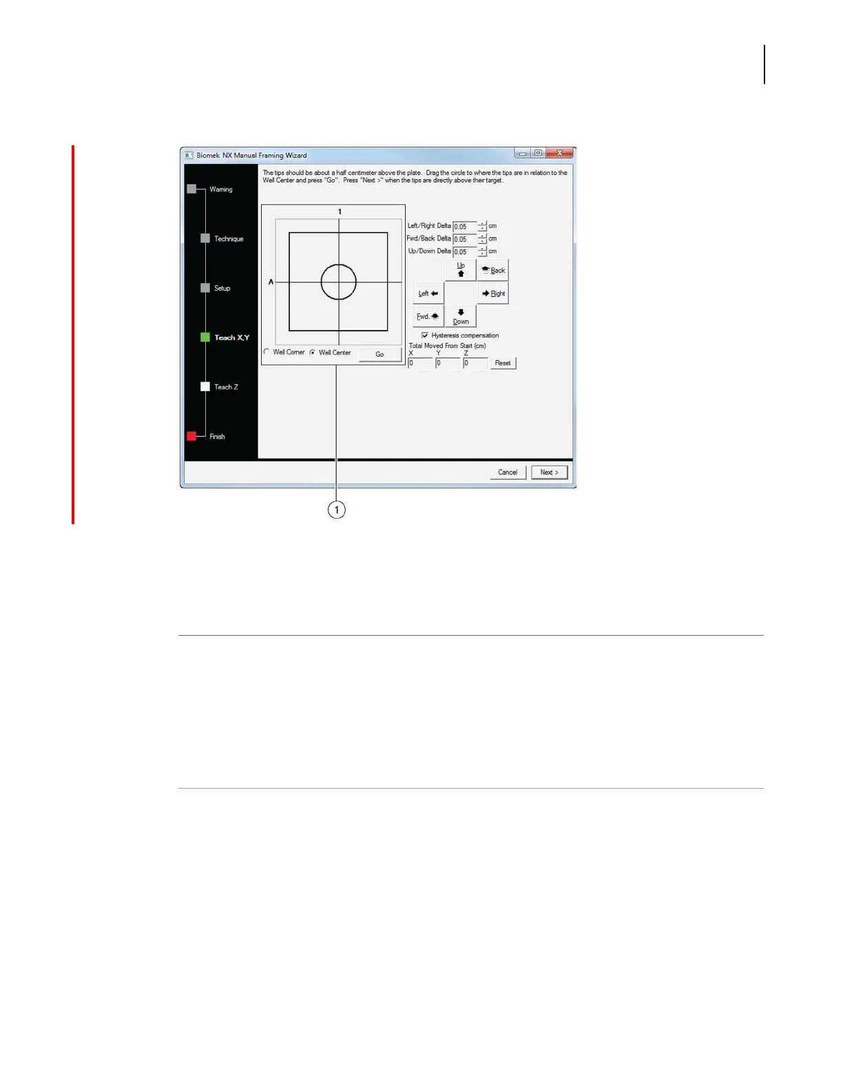
Framing Instructions
Manually Framing Deck Positions on the Biomek NX
3
Figure 3.15 Manual Teaching the X- and Y- axes
To use the graphic alignment tool:
1
Drag the center (small) circle until it represents the tip’s physical position in relation to the
physical position of the wells of the microplate on top of the ALP.
NOTE The small circle represents the tip on the pod. The objective is to provide the software with a
representation of the tip’s position in relation to the physical position of the wells of the microplate
on top of the ALP. The software uses this graphical representation to know approximately how far in
any direction the pod must move to align the tips with the wells of the microplate on top of the ALP.
2
Select Go. The pod moves in accordance with the position of the small circle in relation to the
large circle.
NOTE When the move is completed, the small circle resets itself to the center of the large circle. The
values displayed in Total Moved from Start (cm) changes each time steps 1 and 2 are completed.
If desired, the values in Total Moved from Start (cm) can be reset to zero by selecting Reset.
1. Graphic alignment tool— The graphic alignment tool is a visual
representation of the tip (small circle) and the microplate wells or
corner. The small circle is moved until it represents the tip’s current
physical location in relation to the microplate wells or corner.
 Loading...