Page 7
9487 Dielman Rock Island Ind Dr, St. Louis, MO 63132 www.becs.com
Installation and Technical Manual Rev: H10
S
S
e
e
c
c
t
t
i
i
o
o
n
n
B
B
:
:
W
W
i
i
r
r
i
i
n
n
g
g
t
t
h
h
e
e
B
B
E
E
C
C
S
S
y
y
s
s
3
3
C
C
o
o
n
n
t
t
r
r
o
o
l
l
l
l
e
e
r
r
B – 1: Wiring the Unit
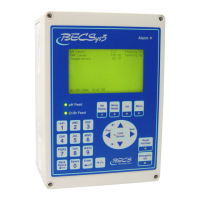
There are several ways that you can wire the relays and
power to the unit. The easiest is to use the cords
already installed in the unit. Plug the AC Cord into a
GFCI outlet (only for low voltage 110VAC-120VAC
applications) and connect the chemical feeders to the
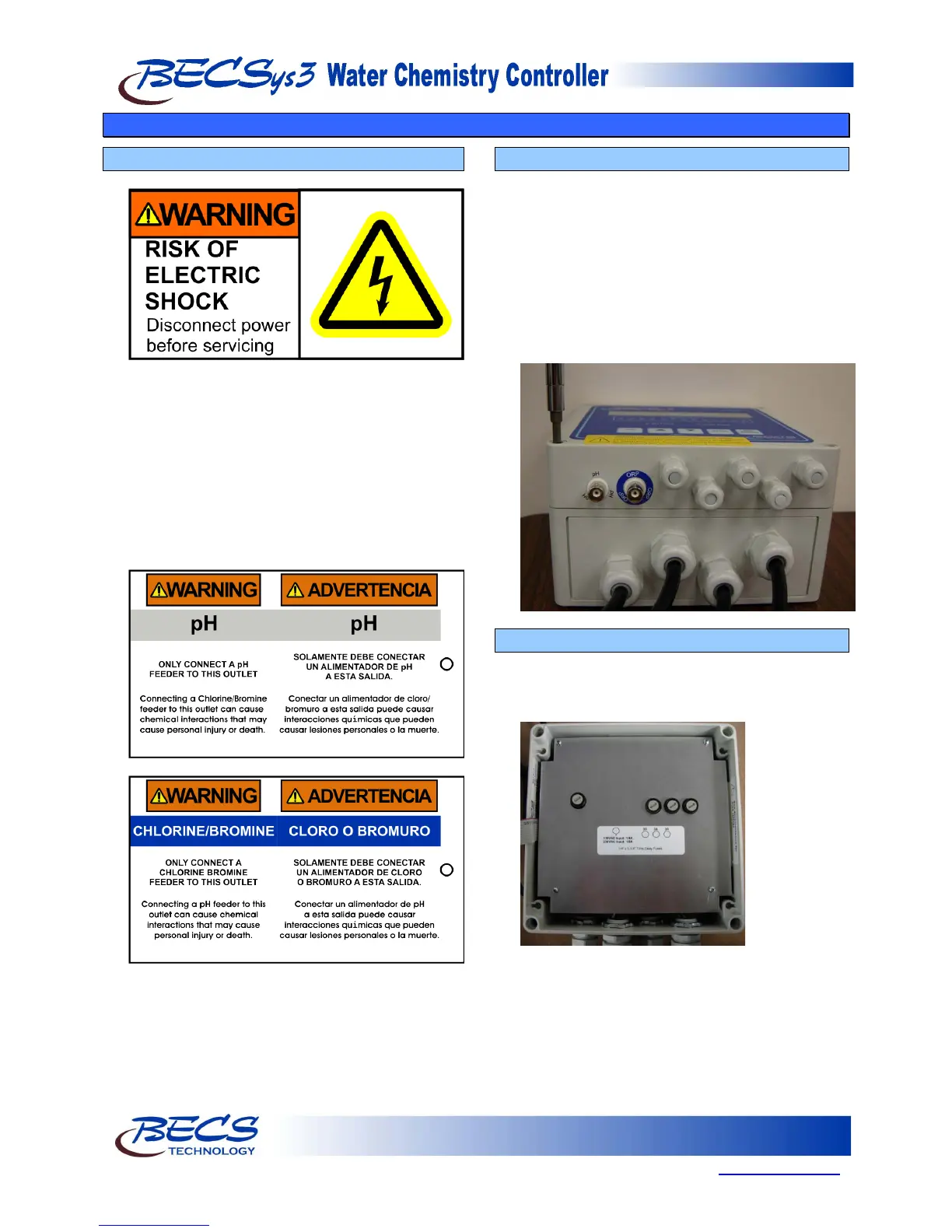
female power cords (pigtails). The pigtails are labeled
with the below warning tags. Be sure to connect the
correct pigtail to the correct chemical feeder. You
must still remove the cover to install the Flow Switch,
and any other optional components.
The second way is to discard the pre-installed cords
and wire the unit directly.
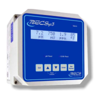
B – 2: Opening the Cover
In order to wire the unit directly or attach the Flow
Switch (and any optional components), you must
open the cover. Remove the cover by loosening the
four screws at the corners with a screwdriver as
shown. NOTE: The screws do not need to be
totally removed, but only loosened. Once the
screws are loosened, carefully lift the top cover off of
the unit. The cover will still be connected to the
base by the ribbon cable. Set the moisture absorbent
packet found inside aside for now.
B – 3: Removing the Safety Shield
To remove the shield, remove the four screws using
a Philips screwdriver. Gently lift the cover straight
up and set it to the side.