Page 8
www.becs.com 9487 Dielman Rock Island Ind Dr, St. Louis, MO 63132
Installation and Technical Manual Rev: H10
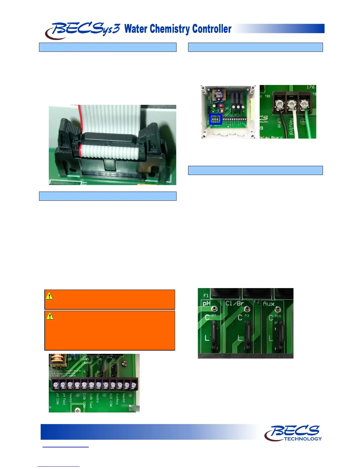
B – 4: Disconnecting the Ribbon Cable
We recommend that you disconnect the ribbon cable
by spreading the two holders at the end of the cable
attached to the cover as shown, unplugging the cable
and removing the cover.
NOTE: Be sure to store the cover in a safe, dry
place while you wire and set up the unit.
B – 5: Wiring Directly to the Unit
To wire the unit directly, you must remove the pigtails
already installed. You may use the ½-inch holes in the
casing to enable you to easily run wires to Terminal
Block 1 (TB1) inside the base of the unit.
NOTE: There are Terminal Blocks labeled TB1
and TB2 in both the cover and base of the
unit and they serve different functions.
Use the ½-inch cord grips provided and whatever
holes are convenient, but when you are all finished
wiring the unit, be sure to plug any unused holes with
a ½-inch NEMA 4x plug.
B – 6: Wiring Power
The main power input should be wired to TB1. The
black wire goes into the position labeled Line, the
white wire goes into the position labeled Neutral, and
the green wire goes into the position labeled Earth
Ground.
NOTE: The black and white wires are colored
brown and blue outside North America.
B – 7: Supplying Power To The Relays
All three of the relays may be configured to be
powered from either the L (Line) connection which
the controller itself is powered from, or their
individual C (Common) connections. As shipped
from the factory, all three relays are configured to be
powered from the L (Line) power connection. If
you wish to use the C (Common) input instead
(commonly used to interlock feeds with the
recirculation pump), you will need to move the black
hat jumpers located above TB2 to their upper
position for the desired relays.
NOTE: The relays inside the controller are solid-
state and can only switch AC signals. If
you need to switch DC power, an
external Mechanical Relay must be used.
Warning: Make sure power is disconnected
while you wire the unit
Warning: Unless specified at time of order,
controllers are configured for 115VAC and
should not be used at 230VAC. Always contact
BECS Technology, Inc. before attempting to
reconfigure a controller’s input supply voltage.