Page 9
9487 Dielman Rock Island Ind Dr, St. Louis, MO 63132 www.becs.com
Installation and Technical Manual Rev: H10
B – 8: Wiring Relay 1
Relay 1 controls pH. You can configure the relay to
be powered from the same Line voltage as the
controller or from its own separate voltage input.
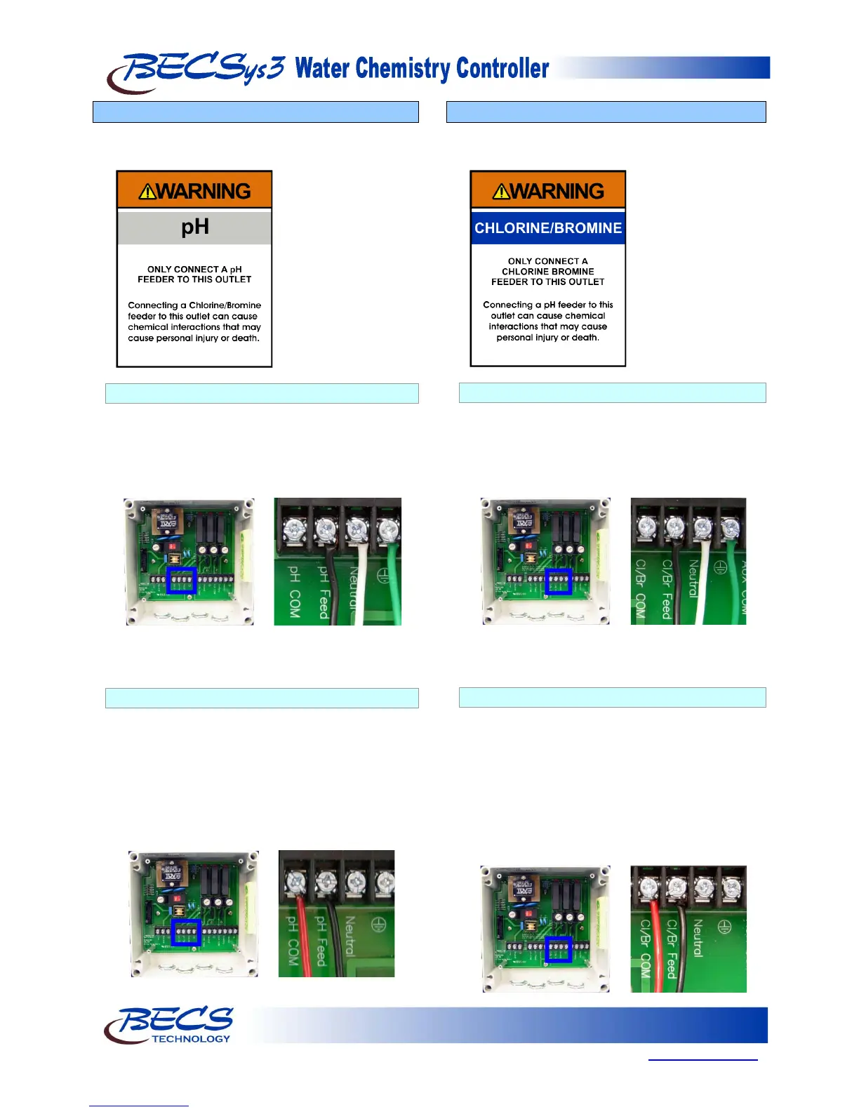
B – 8.1: Line Powered
Make sure the hat jumper is in the lower position
“L”. The black wire goes into the position labeled
pH Feed, the white wire goes into the Neutral
position next to that, and the green wire goes into
Earth Ground position next to that. Nothing
should be connected to the pH COM terminal.
NOTE: The black and white wires are colored
brown and blue outside North America.
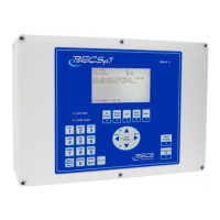
B – 8.2: Common Powered
Connect the incoming power to the pH COM
terminal (the red wire shown below) and move the
hat jumper for the pH relay to the upper position
“C”. The black wire goes into the position labeled
pH Feed. Leave the Neutral and Earth Ground
terminals unconnected inside the controller. The
Neutral and Earth Grounds from the feeder must
be connected to the Neutral and Earth Ground of
the power source supplying this relay.
B – 9: Wiring Relay 2
Relay 2 controls ORP. You can configure the relay
to be powered from the same Line voltage as the
controller or from its own separate voltage input.
B – 9.1: Line Powered
Make sure the hat jumper is in the lower position
“L”. The black wire goes into the position labeled
Cl/Br Feed, the white wire goes into the Neutral
position next to that, and the green wire goes into
the Earth Ground position next to that. Nothing
should be connected to the Cl/Br COM terminal.
NOTE: The black and white wires are colored
brown and blue outside North America.
B – 9.2 Common Powered
Connect the incoming power to the Cl/Br COM
terminal (the red wire shown below) and move the
hat jumper for the Cl/Br relay to the upper
position “C”. The black wire goes into the
position labeled Cl/Br Feed. Leave the Neutral
and Earth Ground terminals unconnected inside
the controller. The Neutral and Earth Grounds
from the feeder must be connected to the Neutral
and Earth Ground of the power source supplying
this relay.